

At 2:15 p.m. you were holding a clean, mirror-finish stainless part. No scratches. At 3:00 p.m., same job, same program, now every flange is sitting at 88° instead of 90°.
Only thing that changed? A 0.030-inch urethane film snapped over the die shoulders.
You didn’t “lose” two degrees. You inserted a soft gasket into a precision mold and expected the mold to behave the same.
I’ve watched operators celebrate the first scratch-free part and miss what happens on the angle gauge. The bend looks good. The surface is protected. But the digital protractor says 88°, not 90°, and now you’re nudging ram depth like you always do.
Listen, if your angles moved the same day you installed film, that wasn’t coincidence—it was compression you failed to program for.
That strip of 0.022- or 0.030-inch urethane doesn’t just sit there. Under load, it compresses unevenly along the die shoulders, effectively widening the V-opening at first contact and then stiffening as tonnage climbs. Your CNC still thinks steel is meeting hardened tool steel. It’s not. It’s meeting something that squishes before it resists.
You solved scratches and introduced a new variable into a closed-loop system that was tuned to thousandths. Did you tell your controller that?
Run this in your head.
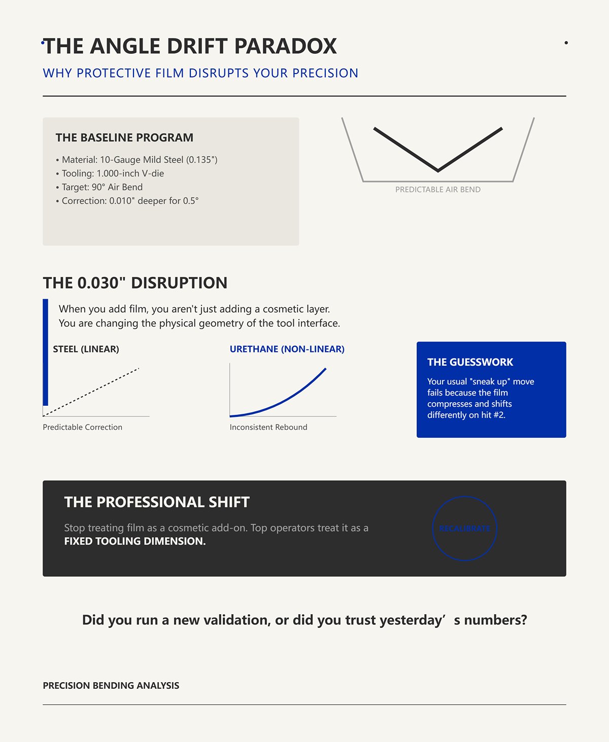
You had a dialed-in program: 10-gauge mild steel, 0.135-inch thick, 1.000-inch V-die, air bend to 90° at a known penetration. First test part always landed at 89.5°, you bumped 0.010 inch deeper, and you were done.
Now add 0.030-inch film.
Your first hit comes out underbent. You try your usual “sneak up” move—reduce or increase penetration by a hair—but the film shifts slightly, or it rebounds differently on the second hit. What used to be a predictable 0.010-inch correction is now guesswork because the compression curve of urethane isn’t linear like steel.
Some operators run film for years without drift. The difference? They treat film thickness as a fixed tooling dimension and recalibrate from scratch on the first bend, not as a cosmetic add-on. Same machine. Different mindset.
When you clipped that film on, did you run a new first-article validation, or did you trust yesterday’s numbers?

I get why shops love the quick strip. A 0.015-inch film for thin aluminum, maybe 0.060-inch for heavier plate. Snap it on. No tool polishing. No dedicated stainless tooling. Feels efficient.
But thickness selection isn’t just about preventing die marks. A 0.022-inch film and a 0.030-inch film don’t just protect differently—they change effective die geometry differently. That’s eight thousandths of an inch. In air bending, that’s degrees.
And here’s the quiet part: film can mask a flexible frame or worn tooling. You see fewer marks, so you assume stability improved. Meanwhile, the machine is still deflecting under load, and now the compressible layer is adding its own deflection profile on top. Two spring systems stacked together.
You’re not adding protection. You’re adding compliance.
Is your press brake rigid enough that adding a soft layer doesn’t amplify deflection at mid-span?
I’ve seen the fix too many times: angles are light, so the operator drives the punch deeper. Five thousandths. Ten. Keep going until the gauge reads 90°.
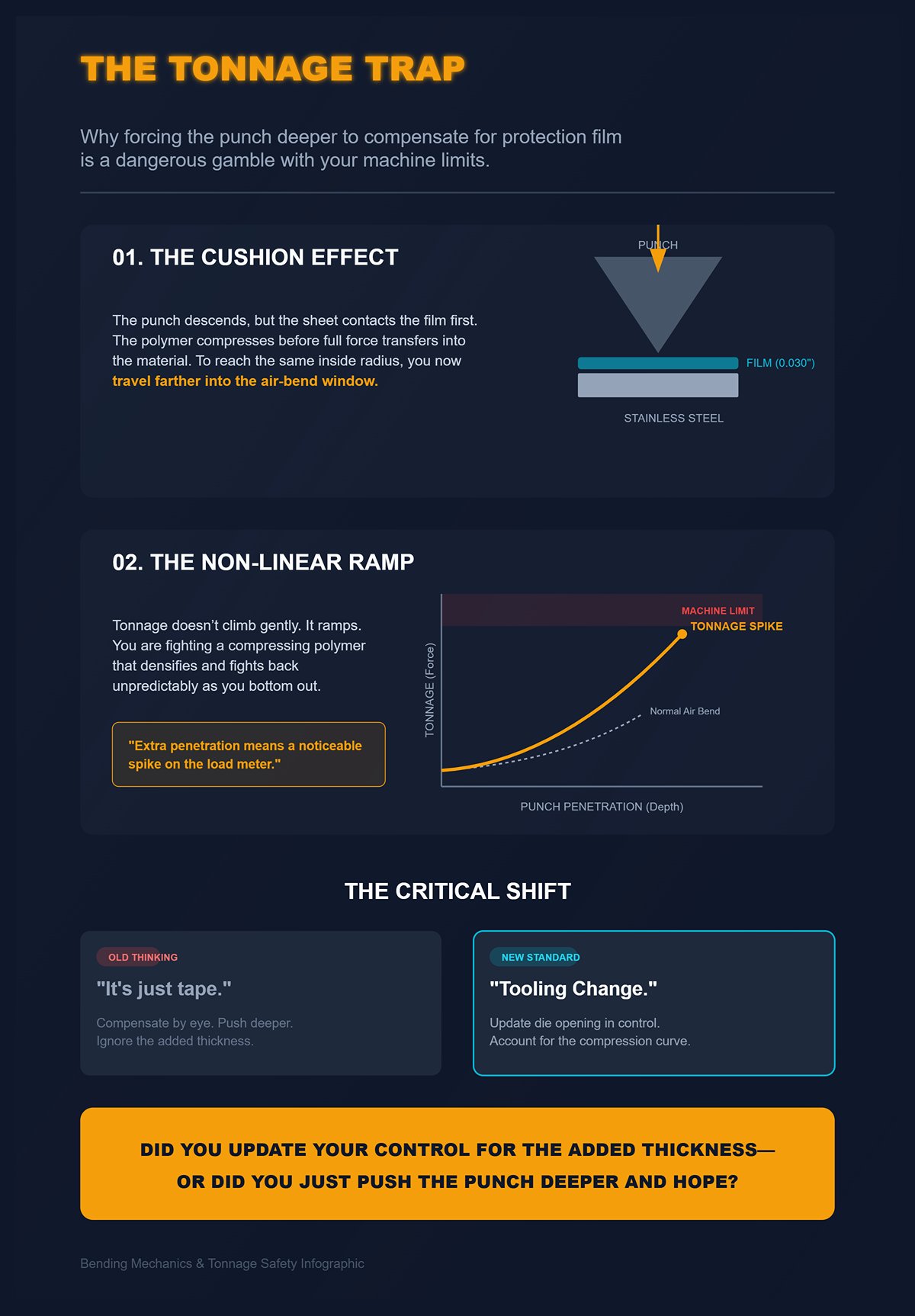
Here’s what’s happening at the bend line. The punch descends, the sheet contacts the film, the film compresses before full force transfers into the material. To reach the same inside radius, you now travel farther. That extra travel increases forming force rapidly as you approach bottom of the air-bend window.
Tonnage doesn’t climb gently. It ramps.
You’re pushing harder not just on steel, but on a compressing polymer that fights back unpredictably as it densifies. On a long 8-foot bend in 304 stainless, that extra penetration can mean a noticeable spike on the load meter. Now you’re closer to tool limits, closer to machine limits, all because you didn’t recalibrate for 0.030 inch of cushion.
This is the shift I need you to make: stop thinking of film as tape, and start thinking of it as a tooling change that demands a new setup sheet.
When you installed your last protection film, did you update your die opening in the control to reflect the added thickness and compression curve—or did you just push the punch deeper and hope?
You want to know how to recalibrate your program when you add urethane so the angle stays put and the load meter doesn’t spike.
Start here: nothing “mystical” is happening. The geometry at the bend line changed before the steel ever yielded. Until you understand exactly where that 0.015 or 0.030 inch goes under load, you’re guessing at ram depth and calling it setup.
I’ve cut apart test bends where we froze the stroke mid-cycle. What you see isn’t a clean V-die imprint. You see a flattened polymer shoulder, steel barely beginning to wrap, and a punch that has traveled farther than your old program ever needed. The film is already deformed before the metal commits to plastic deformation.
That means your controller is solving the wrong triangle.
You used to calculate penetration from a known V-opening, material thickness, and target inside radius. Now there’s a compressible layer reshaping that V dynamically during the stroke. The die opening your CNC thinks is 1.000 inch is not 1.000 inch at contact, not 1.000 inch at half load, and not 1.000 inch at full tonnage.
So when you enter the same numbers and expect the same 90°, what exactly are you bending against?
Take a 1.000-inch V-die and snap on a 0.030-inch film over both shoulders. On paper, you just reduced the opening by 0.060 inch. That’s what most operators assume.
But the first 20–30% of your stroke doesn’t “reduce” the V. It compresses the crown of the film where the sheet first contacts. The material isn’t yet forming; you’re preloading a cushion. The film spreads laterally along the die shoulders, thinning at the apex and thickening slightly toward the flanks.
It doesn’t disappear. It relocates.
Under load, polyurethane behaves viscoelastically. It compresses and flows, then stiffens as it densifies. Early in the stroke, your effective V-opening might behave like 1.020 inch because the sheet is riding on rounded, compressing shoulders instead of sharp steel edges. Deeper in the stroke, once the film is compacted, the opening behaves closer to 0.940–0.960 inch equivalent because the shoulders are now effectively built up.
That means the bend line sees a changing die geometry during a single hit.
And here’s the part most guys miss: because the film compresses more directly under the contact line, the inside surface of the sheet experiences slightly different constraint than it would on hardened steel. Softer interfaces allow more local inward displacement before full support develops, which nudges the neutral axis—the layer that neither stretches nor compresses—closer to the center of the thickness.
Shift the neutral axis and you shift your K-factor.
Did you adjust your bend deduction after installing film, or are you still using the K-factor from bare tooling?
I’ve run 85A durometer urethane and 95A on the same 0.125-inch 5052 job in a 0.750-inch V. Same thickness. Completely different angle behavior.
The 85A felt “forgiving.” No scratches. Operators loved it. But the first hits came out 1.5° light. We added penetration. On long parts, mid-span load climbed faster than expected. The film was acting like a secondary spring stacked on top of the machine’s deflection curve.
The 95A? Less visible compression. Angles were closer to baseline. Less extra stroke required.
Durometer is simply hardness, measured on the Shore A scale for elastomers. Higher number, stiffer material. But stiffness here isn’t just about feel—it defines how much of your ram travel goes into polymer strain before steel strain begins.
Listen, if you’re running a soft 80–85A film on thin stainless, you are spending measurable stroke compressing plastic before you ever reach true forming pressure. You’re pushing harder not just on steel, but on a compressing polymer that fights back unpredictably as it densifies.
That unpredictability is what makes your 0.010-inch correction inconsistent from part to part.
Are you selecting film by “no scratches,” or by durometer matched to material thickness and tonnage range?
Let’s get specific.
You’re air bending 0.135-inch 304 stainless in a 1.000-inch V. Baseline penetration for 90° might be, hypothetically, 0.350 inch from material contact point. Now you add 0.015-inch film per shoulder—0.030 inch total stack.
If that film compressed to zero, you’d just subtract 0.030 from your opening and adjust bend calculations accordingly. Clean math.
But it doesn’t compress to zero. Under working tonnage, maybe it compresses 40–60% depending on durometer and load per inch. So your effective V-opening might behave like 0.970–0.985 inch at forming load—not 1.000, not 0.970 consistently, but somewhere in between depending on part length and tonnage distribution.
Smaller V-opening in air bending means tighter inside radius and greater springback forces. To hit the same 90°, you often need deeper punch penetration because the system absorbed some stroke in compression early, then stiffened late.
That extra 0.010–0.020 inch of ram travel doesn’t sound like much.
On an 8-foot bend in stainless, it can mean several extra tons per foot as you approach the bottom of the air-bend window.
Now stack that on a machine already compensating for frame deflection and crowning. You’ve introduced a variable V-die width that changes with load. Your CNC’s tonnage-based angle correction is working off steel-to-steel assumptions.
Did you enter a new effective die width in the control and validate with test coupons—or are you still telling the machine it’s a 1.000-inch V because that’s what’s stamped on the tool?
Bend a 0.090-inch 5052-H32 part with bare tooling. Measure springback. Now run the same job with a soft 0.030-inch film. Many shops report the film “makes it underbend more.”
Here’s why.
Springback is elastic recovery after load removal. The tighter the elastic strain stored in the outer fibers, the more it wants to open. When you introduce a softer interface, two things happen:
First, early-stage compression in the film delays full plastic engagement of the metal. You spend part of the stroke building pressure in the polymer instead of driving strain into the sheet.
Second, reduced friction at the die shoulders—because urethane conforms and distributes pressure—allows slightly more material flow during bending. Less constraint at the contact points means the sheet can recover more freely once unloaded.
On stainless, which already has higher yield strength and pronounced springback, that softer interface exaggerates the effect. On aluminum, especially tempers like 5052 or 6061-T6, the difference between a hard steel shoulder and a cushioned one shows up as an extra degree or two of opening unless you compensate.
That’s why some shops swear film “always underbends stainless.”
It’s not superstition. It’s stored elastic energy and altered constraint conditions.
So when you clip on that strip and chase 90° by feel, are you accounting for increased springback in your angle correction table—or are you still reacting part by part, wondering why yesterday’s numbers don’t land today?
You want to know how to recalculate ram depth, effective die width, and bend deduction so the angle lands the same every time with film installed.
Start here: the thickness you clip on the die shoulder is not protection. It’s geometry.
I’ve run the same 0.135-inch 304 stainless job in a 1.000-inch V with three films: 0.015, 0.030, and 0.040 inch. Same punch. Same tonnage curve. Same CNC program. Only the film changed. The 0.015 needed about 0.008–0.010 inch additional penetration to hit 90°. The 0.030 needed closer to 0.015–0.020. The 0.040? It was a different animal—over 0.025 inch deeper, and the inside radius grew enough that our bend deduction was off by more than 0.030 inch on a 10-inch flange.
That’s not “surface protection.” That’s a soft gasket inserted into a precision mold. Every thousandth of cushion changes the cast.
Here’s the mechanism: thicker film means more stroke is spent compressing urethane before steel yields. Compression is not linear. At low load, it collapses easily; at higher load, it stiffens fast. So your effective V-opening under working tonnage is no longer a clean subtraction of film thickness—it’s a load-dependent value. That means your CNC’s air-bend model, which assumes a fixed die width and steel-to-steel contact, is solving the wrong triangle.
And the thicker the film—.020, .030, .040 inch and beyond—the more you are bending against urethane before you ever bend steel.
So the trade-off isn’t just durability versus scratches. It’s durability versus predictability. Which one are you optimizing for on your current machine?
Picture a 0.012-inch polyurethane strip, Shore 90A, on a 0.750-inch V forming 0.090-inch 5052. First 50 parts? Beautiful. Angles within 0.5°. Minimal extra stroke—maybe 0.006 inch beyond bare-tool baseline. Bend deduction shift small enough that you can compensate with a slight K-factor tweak.
Why so stable?
Because thin film behaves closer to a compliant coating than a structural layer. Strain in a bent polymer scales with thickness over radius. Double the thickness, double the surface strain at the same bend radius. Keep it thin and the polymer flexes instead of crushing. In actuator testing I’ve seen, 50-micron layers allowed significantly larger deformation before restricting motion compared to 130-micron layers. Translate that to the brake: thin film interferes less with the steel’s natural bend path.
But here’s the shop-floor truth.
Run that same 0.012 on 0.125-inch HRPO with laser-cut edges and you’ll start seeing witness lines in under 200 hits. Not because it’s “weak,” but because sharp edges concentrate stress. The film’s thin cross-section means higher localized strain per cycle. Micro-tears form. Once the surface scars, compression becomes uneven, and your angle drift begins—0.3° here, 0.7° there.
Thin film gives you the cleanest geometry shift and the easiest math: measure added penetration to reach target angle, record new effective die width based on compression at forming tonnage, adjust bend deduction accordingly. But it won’t tolerate abuse.
Are your parts edge-broken and deburred before they ever touch that 0.015-inch strip?
Now we’re in the range most shops call “standard.” A 0.030-inch, 85A strip on a 1.000-inch V. No scratches. Operators relax.
Then the digital protractor says 88°, not 90°, and now you’re nudging ram depth like you always do.
Mid-range film is thick enough that compression becomes a structural phase of the bend. On a 10-foot 304 stainless part at, say, 12 tons per foot, that 0.030 doesn’t just flatten—it densifies. Early stroke: soft. Mid-stroke: progressively stiffer. Bottom of the air-bend window: it’s pushing back hard. You’re pushing harder not just on steel, but on a compressing polymer that fights back unpredictably as it densifies.
Mechanically, three things shift:
This is where bend deduction errors stack up. If your baseline BD assumed, say, a 0.160-inch inside radius in a 1.000-inch V, and the compressed film effectively behaves like a 0.970–0.980 V, your radius and K-factor move. Not wildly—but enough that flange lengths miss by 0.020–0.040 inch on longer legs.
Mid-range film can survive 500-part runs if the polymer toughness is good. Some high-yield variants hold curvature for thousands of cycles without cracking. But durability of the material is not the same as geometric neutrality in the process.
Did you enter a new die width in your control based on measured angle versus penetration with that 0.030 installed—or are you still telling the CNC it’s a 1.000-inch V because that’s what’s stamped on the steel?
I’ve seen shops throw 0.060-inch film on stainless architectural panels because they’re terrified of scratches.
First hit on 0.125-inch 304 in a 1.250-inch V: angle comes out light by nearly 3°. They add stroke. Tonnage spikes late in the bend. Inside radius measures larger than expected, not smaller.
That surprises people.
Here’s why. With very thick film, you’re no longer simply narrowing the V-opening—you’re creating a compliant die shoulder that wraps the sheet differently. The contact patch widens. Pressure distributes. The steel is less sharply supported at the edges, so instead of forming tightly against a crisp steel shoulder, it’s bending against a deforming cushion. The result can be a larger effective inside radius, even though penetration increased.
And because strain in the polymer increases with thickness at a given bend radius, heavy films experience high internal stress. Under repeated 90° cycles, thicker layers can fatigue faster than expected. The “heavy-duty equals longer life” assumption doesn’t always hold when the strain per cycle climbs exponentially with thickness-to-radius ratio.
You get durability against scratching, yes. But you pay in:
Listen, if you install 0.040-inch film and don’t recharacterize your bend from scratch—test coupons, angle versus depth chart, revised BD—you’re not protecting quality. You’re hiding instability under a soft surface.
How much extra penetration are you adding right now on your thickest film, and have you actually measured the resulting inside radius with calipers?
Run a plain 0.030-inch strip for 300 parts on 11-gauge mild steel. You’ll start seeing it creep sideways in the die, especially on long parts. Compression plus shear at the shoulder walks it. Once it shifts, your effective die width changes from left to right. Angles vary across the length.
Switch to a cloth-backed version. The fabric limits stretch. Dimensional stability improves. It stays put.
But there’s a catch.
Cloth backing reduces the film’s ability to conform fully to micro-geometry in the die shoulder. Slightly less compression. Slightly stiffer interface. On delicate brushed stainless, that can mean higher localized pressure if the die shoulder isn’t perfectly clean. Protection versus conformity.
For high-volume runs—500 parts and up—stability matters more than theoretical softness. A film that creeps 0.010 inch sideways has just changed your die geometry mid-run. That’s worse than a slightly stiffer surface that stays consistent.
So when you spec film for a long job, are you choosing based on scratch fear alone—or on how that material behaves after 400 cycles at full tonnage on your specific V-opening?
| Aspect | Plain Polyurethane (0.030″) | Cloth-Backed Polyurethane |
|---|---|---|
| Performance in 300+ Part Runs | Begins creeping sideways in the die, especially on long parts | Remains stable and stays in place |
| Behavior Under Compression & Shear | Shifts at the shoulder; effective die width changes | Fabric backing limits stretch and movement |
| Dimensional Stability | Reduced over time; angle variation across part length | Improved stability; consistent angles |
| Conformity to Die Micro-Geometry | Better conformity; softer interface | Slightly reduced conformity; stiffer interface |
| Surface Pressure on Delicate Finishes | Lower localized pressure if clean | Potential for higher localized pressure if die shoulder isn’t perfectly clean |
| Suitability for 500+ Part Runs | Geometry can change mid-run due to creep (e.g., 0.010″ shift) | Maintains consistency under full tonnage |
| Best Selection Criteria | Prioritizes softness and scratch protection | Prioritizes stability and consistency in long runs |
You want numbers, not philosophy. Good.
Last month I stood behind a 135-ton brake running 0.079-inch (2mm) 304 in a 1.000-inch V with 0.022-inch urethane installed. First hit: 87.6°. Operator adds 0.012 inch of ram depth. Second hit: 90.3°. He backs it off 0.004. Now we’re chasing thousandths like it’s a game.
The right question isn’t “How much more stroke?” It’s: what triangle is your controller solving right now—and is that triangle real?
This protocol turns film into a programmed variable. Z-offset. Effective V-opening. Revised bend deduction. If you skip that math, you’re not bending—you’re gambling first articles and calling it experience.
Before we touch the control, we settle one argument.
Take that same 2mm sheet. Standard air-bend guidance says a V-opening of 6–8× thickness for thin stock. Call it 12–16mm. A 1.000-inch V (25.4mm) is already wide—fine for stainless to control tonnage and radius.
Now add 0.022-inch film. That’s 0.56mm per side if it’s lining both shoulders. Under load, maybe it compresses to 0.30–0.40mm depending on durometer and tonnage per foot.
Does that make your material 2.56mm thick?
No. The steel’s yield strength didn’t change. Springback behavior didn’t suddenly match 2.5mm stock. What changed is the geometry the steel “sees” at the die shoulders.
So you treat film as part of the die stack, not the material stack.
Why that distinction matters: tonnage formula is sensitive to thickness squared. P = 650 × S² × L / V. If you lie to the control and bump material thickness to compensate for angle loss, the machine calculates higher tonnage than the steel needs. On thin gauge, that percentage jump is significant. A 0.022-inch layer on 0.079-inch stock is a 28% increase relative to thickness if you misclassify it. That’s how people drift toward overload instead of recalibration.
Listen, film does not add strength. It adds compliance at the contact interface.
So when you open your tooling library, are you editing material thickness—or are you creating a new die entry that reflects a different effective V and penetration curve?
We start with something you can measure.
Cut a 4-inch coupon. Install fresh film. Bring the punch down until it just kisses the sheet—no load. Zero your Z.
Now air-bend to 90° using your existing program and record two numbers: achieved angle and actual ram penetration from zero.
Say your baseline (no film) program hit 90° at 0.615-inch penetration in that 1.000-inch V. With 0.022-inch film installed, you hit 90° at 0.628-inch.
Difference: 0.013 inch.
That 0.013 is not random. It is the compressed film thickness at working load plus any shift in the contact geometry.
Do this three times. Average it. If you see 0.012, 0.014, 0.013—good. Your film is stable. If you see 0.010, 0.018, 0.015—your polymer is moving or densifying unpredictably.
Your starting Z-offset equals the measured penetration delta, not the nominal film thickness.
Nominal 0.022 does not matter. Compressed 0.013 does.
Now we refine the effective V-opening. A simple working approximation for air bending: inside radius ≈ 0.16 × V for stainless in a standard setup. Measure your actual inside radius with film installed. If your baseline radius in a 1.000 V was 0.160 inch and now you’re measuring 0.150, your effective V is behaving closer to 0.937 (because 0.150 / 0.16 ≈ 0.937).
That becomes a new die entry in your CNC: “1.000 V + 0.022 film (compressed).” Not a note. A separate tool.
Because the controller is calculating bend angle from punch penetration relative to assumed V-width. If you leave it at 1.000, it’s solving the wrong triangle.
Have you actually measured compressed thickness at tonnage—or are you programming from what’s printed on the film box?
Now we deal with flat pattern.
Your previous bend deduction (BD) assumed a known inside radius and K-factor. Let’s say for that 2mm 304 in a 1.000 V you were using a K of 0.42 and getting consistent flange lengths.
With film installed, you measured a tighter inside radius—0.150 instead of 0.160. That alone changes bend allowance.
Bend allowance = (π/180) × angle × (R + K × T).
Change R by 0.010 inch and the allowance shifts immediately. On a 90° bend:
ΔBA ≈ (π/2) × 0.010 ≈ 0.0157 inch.
That’s over 0.015 inch difference in developed length from radius change alone. Now add any K-factor shift due to altered strain distribution from the compliant interface, and you’re easily in that 0.020–0.040 inch miss on longer flanges.
This is why parts suddenly grow or shrink when you “just add film.”
Run two test blanks: one baseline, one with film. Measure actual flange lengths after bending. Back-calculate your real K with film in place. Lock that into a separate material-tool combination in your CAM or control.
Film installed = new BD table.
Otherwise you’re protecting the surface and quietly stretching or shrinking every leg on the print.
When you switch jobs, do you load a new BD tied to that film thickness—or are you trusting tribal memory?
Single bends lie. Boxes tell the truth.
Imagine a four-sided cover in 0.063-inch aluminum with 0.015-inch film—thin, “safe,” right? On thin gauge, that film might represent 20–25% of material thickness before compression. Even if it crushes to 0.008 under load, variability of 0.002 inch between first and last bend is realistic as the film work-hardens.
First bend: compressed thickness 0.008. Fourth bend: maybe 0.010 because the strip has densified along the shoulders.
That 0.002 difference in penetration translates into angle variation—maybe 0.4–0.6°. On a return flange, that stacks. By the time you close the box, you’re fighting a 0.030-inch gap at the seam.
You blame backgauge repeatability. You blame springback.
But the real variable was a soft interface changing over cycles.
On high-strength 3mm parts, that variability is a small percentage of thickness. On 1.5mm aluminum, it’s a big one. Thin gauge suffers more because the film is a larger fraction of the stack height.
Listen, recalibration gets you a controlled starting point. It does not eliminate polymer creep, heat buildup, or compression set over 500 cycles. That’s a physical limit, not a programming one.
So before you launch a 1,000-part run with film installed, have you tracked angle drift from part 1 to part 200 on the same strip—or are you assuming your first-article correction holds forever?
You want to know how to control or monitor film compression drift during long runs so your angles don’t creep.
Here’s the hard truth: you can monitor it, you can chart it, you can sample every 25 parts with a digital protractor—but once the film crosses its mechanical limit, the drift doesn’t creep.
It jumps.
Think of that urethane like a soft gasket inserted into a precision mold. At light, predictable load it compresses and behaves. Past a certain pressure, it doesn’t just get thinner; it starts to move sideways, cold-flow, shear at the tape line, and pack into the V like chewing gum under a boot. That’s the breaking point. And when it happens, your nice, averaged 0.013-inch penetration delta becomes 0.018 on one hit and 0.011 on the next.
This is where “No scratches” quietly turns into angular scrap.
So where does it actually fail in the real world?
Take 10-gauge A36 in a 1.000-inch V on a 175-ton brake. You’re running 6-foot parts, flirting with 70 to 90 tons across the bed depending on material variance. With 0.030-inch urethane installed, your first ten parts look stable. You did the math. You programmed the offset. You feel smart.
Then around part 30, your angle is suddenly 1.2° open.
Not 0.2. Not gradual. A full degree plus.
What happened isn’t mysterious. Under high surface pressure at the die shoulders, the urethane exceeds its compressive strength and begins to extrude into the V opening. Material that used to sit neatly between sheet and die is now being squeezed forward and downward. That changes the contact line. Your effective V is no longer what you measured at setup.
You’re pushing harder not just on steel, but on a compressing polymer that fights back unpredictably as it densifies.
The extrusion isn’t uniform across the bed, either. If your tonnage curve peaks near center, the film will thin more there. Now your angles vary left to right. The controller thinks the tool is rigid. It isn’t. You’ve introduced a load-sensitive cushion into a process that assumes hardened steel geometry.
And here’s the part most shops miss: once extrusion starts, it accelerates. The more it flows, the less cross-sectional thickness remains to resist further flow. That’s why the batch splits—first 40 parts within tolerance, next 60 chasing the ram depth.
Are you logging tonnage per foot on these jobs and correlating it to angle shift—or are you just watching the protractor and reacting?
Now shrink the V.
Drop to a 0.500-inch V to chase a tight inside radius on 0.090-inch 304. The die shoulders are closer, the included angle steeper at contact, and the film has less room to sit flat. It’s forced to bend sharply over the die radius before the metal even yields.
That’s where buckling starts.
Film is flexible, not magical. When you drape 0.022-inch urethane over a narrow V and drive a punch into it, compressive stress builds along the shoulders. If the film can’t stretch enough to conform, it wrinkles microscopically. Those wrinkles become pressure ridges. Pressure ridges become witness lines.
So you added film to prevent die marks—and still get faint imprints.
Because in a tight V, the film isn’t just compressing; it’s being folded into a geometry it can’t smoothly occupy. The tighter the radius requirement, the less forgiving that interface becomes. Your measured compressed thickness at setup doesn’t represent what’s happening at peak load on the shoulders.
Listen, in narrow V work the film behaves less like a uniform layer and more like a shifting membrane.
Are you checking inside radius and surface condition at the die shoulder under magnification—or assuming “film equals safe” no matter the V-width?
High tonnage causes jumps.
Long runs cause drift.
Picture 0.063-inch aluminum with 0.015-inch film, 800 parts, four bends each. That’s 3,200 hits on the same strip of polymer if you’re not advancing it. Every hit compresses, relaxes, and heats the urethane slightly. Polymers don’t like that cycle. They take a compression set—a permanent reduction in thickness after repeated load.
Hypothetical but realistic: your initial compressed thickness measured 0.008 inch. After 400 cycles in the same zone, it’s effectively 0.0065. That 0.0015-inch loss at the interface changes penetration. On a 90° air bend, that can mean roughly 0.3–0.5° difference depending on V and material.
Small number. Big consequence.
But the drift isn’t linear. Early in the run, the film settles quickly. Then it stabilizes. Then, as micro-tearing and surface glazing develop, friction changes and compression behavior shifts again. That’s why part 1, part 200, and part 700 don’t tell the same story.
You can monitor this. Pull angle samples every 50 pieces. Track required ram correction. Advance the film strip every 100 hits. Some shops even treat film like consumable tooling and change it at a fixed cycle count.
But none of that makes it universal.
It just manages decay.
And once you accept that film has a mechanical life under load—defined by tonnage, V-width, and cycle count—you stop asking how to “set it and forget it.”
You start asking whether a soft, sacrificial layer is the right solution for the job at all.
So on your next 1,000-piece stainless run, are you treating that urethane like precision tooling with a service life—or like tape you throw over the die and hope behaves?
You’re asking the right question now: if film has a mechanical life and a failure curve, what replaces it when the job can’t tolerate drift?
Here’s the shift that took me years to accept. Protection is only worth keeping if it’s predictable. If the layer between your sheet and your die changes thickness under load, across the bed, or over time, you haven’t solved scratches—you’ve inserted a soft gasket into a precision mold and hoped the casting still lands true.
Permanent tooling upgrades aren’t about being fancy. They’re about moving the variable out of compression and into geometry you can measure with a micrometer instead of guessing with a protractor. So which path actually controls thickness instead of reacting to it?
Film thickness is nominal. It says 0.015 inch on the box. You measure 0.0145 in one spot, 0.016 in another. Then you load it, and that number stops meaning anything because compression depends on tonnage per foot.
A urethane V-die is different. The polymer is the die, not a skin taped over steel. Its hardness—say 90A versus 95A Shore—is specified. Its geometry is machined or cast to a defined V-opening. When it compresses, it does so as a bulk material with known durometer behavior, not as a thin membrane that can wrinkle, extrude, or take a set unevenly.
That doesn’t make it rigid. It makes it characterizable.
Listen, the first time you swap a steel 1.000-inch V plus 0.030-inch film for a purpose-built urethane die, your tonnage curve changes. Required force often drops. If your brake is marginal on thicker stock, you may suddenly find you’re under-tonnaging and not hitting depth. That’s not a flaw in the die—that’s a compatibility gap in your setup. Your CNC was calibrated around steel bottoming characteristics, not elastic tooling.
So the comparison isn’t “cheap film versus expensive die.” It’s “variable compressed layer versus defined elastic geometry.” One drifts mid-run. The other shifts your baseline and stays there.
Are you running a brake with enough control resolution—and enough available tonnage margin—to program around an elastic die on purpose, or are you barely holding angle now with steel?
| Aspect | Adhesive Films | Urethane V-Dies |
|---|---|---|
| Nominal Thickness | Listed (e.g., 0.015 in) but varies in reality (e.g., 0.0145–0.016 in) | Defined by machined or cast V-opening geometry |
| Behavior Under Load | Compression varies based on tonnage per foot; thickness loses predictability | Compresses as a bulk material with known durometer behavior |
| Material Characteristics | Thin membrane; can wrinkle, extrude, or deform unevenly | Polymer body acts as the die itself; hardness specified (e.g., 90A vs. 95A Shore) |
| Predictability | Variable compressed layer; may drift mid-run | Defined elastic geometry; shifts baseline but remains stable |
| Rigidity | Flexible and inconsistent | Not rigid, but characterizable and consistent |
| Impact on Tonnage | Maintains standard steel bottoming tonnage expectations | Often reduces required force; tonnage curve changes |
| Setup Compatibility | Works within existing steel-based CNC calibration | Requires recalibration for elastic tooling behavior |
| Risk Factors | Thickness variation affects angle control | Under-tonnaging possible if brake lacks sufficient margin |
| Cost Framing | Lower upfront cost | Higher upfront cost |
| Real Comparison | Variable compressed layer | Defined elastic geometry |
Polished 304 doesn’t care about your excuses. It cares about contact pressure and sliding.
A rolling V-die changes the physics. Instead of dragging the sheet across fixed shoulders, the shoulders rotate. Contact becomes rolling instead of sliding. Surface pressure distributes differently. The finish survives because friction drops, not because you padded the die.
That means no compressing layer to densify. No gradual thickness loss. The geometry the controller sees on part one is the same on part five hundred.
Nylon inserts attack the same problem from another angle. You machine a steel die body with a pocket and lock in a replaceable nylon strip—say 0.250 inch thick, captured mechanically so it can’t creep forward. Now the protective material has a defined cross-section and is supported on all sides. It doesn’t extrude into the V because it is the V surface.
When it wears, you replace the insert. You don’t chase angle for three hours wondering why “No scratches” turned into 88.7° on a 90° callout.
Are you protecting the surface by reducing friction and controlling contact—or by stuffing something soft between two hard tools and hoping it behaves?
Here’s the lens I want you to carry forward: protection must be engineered like tooling, not applied like tape.
If you choose a urethane die, you qualify it. You run a controlled test bend at known tonnage per foot. You log penetration depth to achieve 90.0°. You record springback with that exact material lot. That program becomes “Urethane V 1.000-90A,” not “1.000 V with film.”
If you install a rolling V-die, you validate angle versus depth across the bed and confirm crowning response, because rolling contact can shift load distribution slightly. Then you lock it in as a separate tool library entry.
If you spec nylon inserts, you define a wear inspection interval—every 300 hits, every shift, whatever your data supports—and you treat insert thickness like you would a ground punch radius.
The non-obvious part? You’re not eliminating adjustment. You’re moving it to the front of the job, where it’s controlled, documented, and repeatable.
But the digital protractor says 88°, not 90°, and now you’re nudging ram depth like you always do. The difference is whether you’re compensating for a known elastic system you qualified—or chasing a polymer that’s changing under your feet.
So look at your next polished stainless run and answer this without flinching: are you engineering surface protection as a defined tool in your library, or are you still treating it like a consumable bandage over hardened steel?


