

A kid on second shift punched 0.250″ mild steel into the company’s shiny “one-click” calculator. Came back with 82 tons. Machine was rated for 100. Green light.
Halfway through the first bend the shop floor jumped like someone dropped an anvil. The 4-way die split at the shoulder. Not chipped. Split. We swept up five grand in carbide and two weeks of lead time.
The calculator didn’t lie. It answered a narrower question than the one that keeps your tooling alive.
Here’s what that calculator actually did.
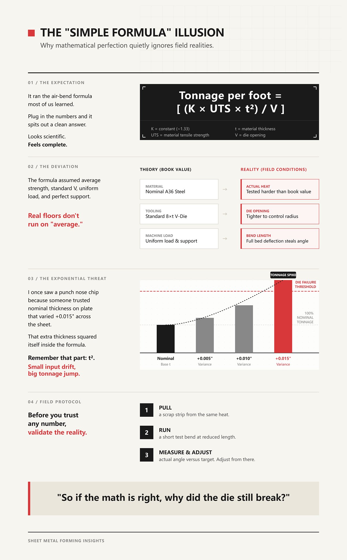
It ran the air-bend formula most of us learned: Tonnage per foot = [ (K × UTS × t²) / V ]
Where:
[K] = constant (about 1.33 for air bending)
[UTS] = material tensile strength
[t] = material thickness
[V] = die opening
Plug in the numbers and it spits out a clean answer. Looks scientific. Feels complete.
But on that job, the print said “A36.” The heat we got tested harder than book value. The die opening wasn’t the nominal 8× thickness — it was tighter to control radius. And the bend length ran almost full bed, where deflection starts stealing angle unless you’ve got dynamic crowning dialed in.
The formula assumed average strength, standard V, uniform load, perfect support.
Real floors don’t run on “average.”
I once saw a punch nose chip because someone trusted nominal thickness on plate that varied +0.015″ across the sheet. That extra thickness squared itself inside the formula. Remember that part: t². Small input drift, big tonnage jump.
Before you trust any number, pull a scrap strip from the same heat and run a short test bend at reduced length. Measure actual angle versus target. Adjust from there.
So if the math is right, why did the die still break?
A calculator estimates forming force. A safe setup respects machine and tooling limits.
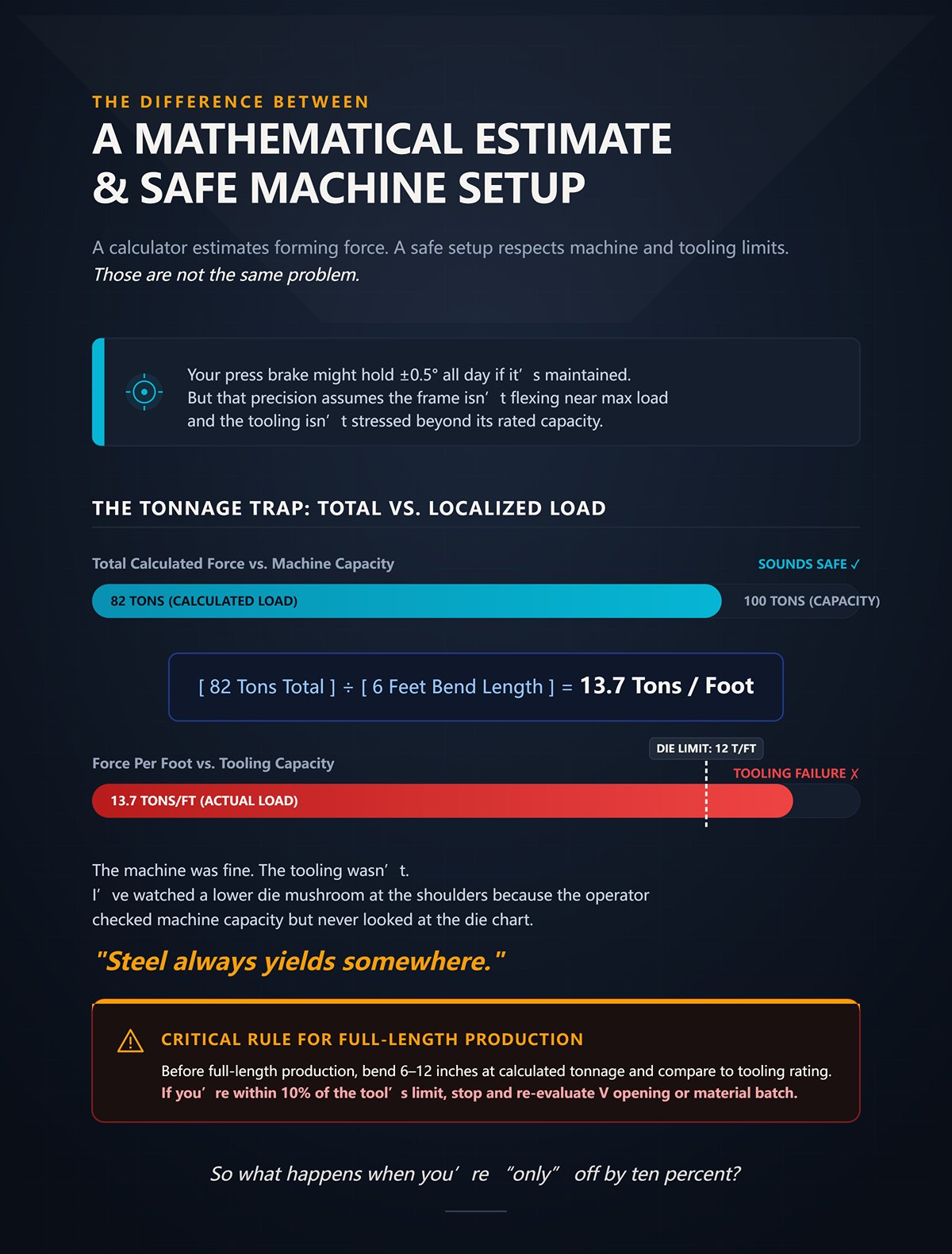
Those are not the same problem.
Your press brake might hold ±0.5° all day if it’s maintained. Maybe tighter with laser feedback and crowning behaving. But that precision assumes the frame isn’t flexing near max load and the tooling isn’t stressed beyond its rated capacity.
The calculator gave us 82 tons total. Sounds safe on a 100-ton machine.
But break it down: [Total tonnage] ÷ [Bend length in feet] = [Tons per foot]
If we ran 6 feet: [82 tons] ÷ [6 ft] ≈ [13.7 tons/ft]
That die was rated for 12 tons per foot.
The machine was fine. The tooling wasn’t.
I’ve watched a lower die mushroom at the shoulders because the operator checked machine capacity but never looked at the die chart. The press survived. The die didn’t. Steel always yields somewhere.
Before full-length production, bend 6–12 inches at calculated tonnage and compare required force to tooling rating per foot. If you’re within 10% of the tool’s limit, stop and re-evaluate V opening or material batch.
So what happens when you’re “only” off by ten percent?
Let’s say the real requirement was 90 tons. Calculator said 82. That’s about a 10% miss.
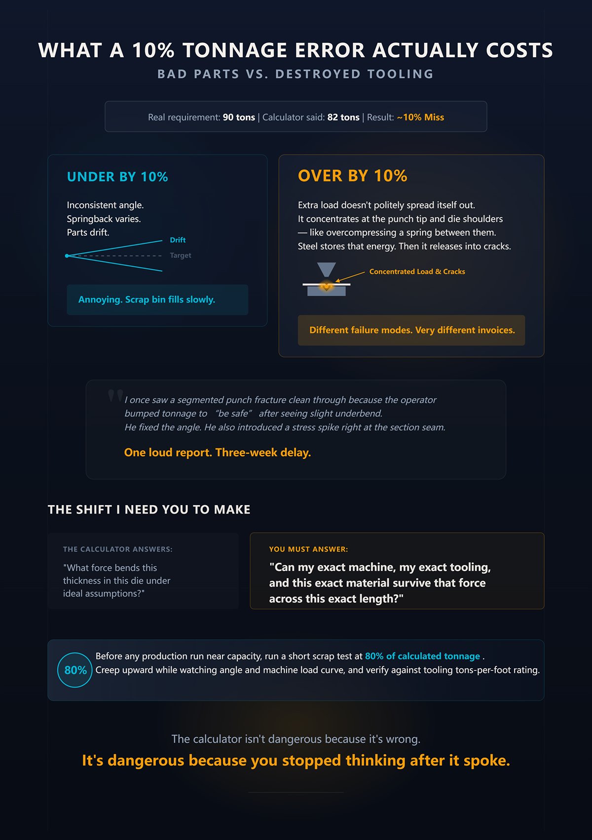
If you’re under by 10%, you get inconsistent angle. Springback varies. Parts drift. Annoying. Scrap bin fills slowly.
If you’re over by 10% near a tooling limit, that extra load doesn’t politely spread itself out. It concentrates at the punch tip and die shoulders — like overcompressing a spring between them. Steel stores that energy. Then it releases into cracks.
Different failure modes. Very different invoices.
I once saw a segmented punch fracture clean through because the operator bumped tonnage to “be safe” after seeing slight underbend. He fixed the angle. He also introduced a stress spike right at the section seam. One loud report. Three-week delay.
Here’s the shift I need you to make: the calculator answers “What force bends this thickness in this die under ideal assumptions?” You must answer “Can my exact machine, my exact tooling, and this exact material survive that force across this exact length?”
Before any production run near capacity, run a short scrap test at 80% of calculated tonnage, creep upward while watching angle and machine load curve, and verify against tooling tons-per-foot rating.
The calculator isn’t dangerous because it’s wrong.
It’s dangerous because you stopped thinking after it spoke.
You want a systematic process, not another lecture about “be careful.”
Good. Then we start by pulling the formula apart until you can see where it lies to you.
On a job a few years back, we were bending 3/16″ plate, nothing exotic, long straight flange. Calculator said 58 tons total. Machine could do 90. Operator felt safe. Halfway through the run, angle drifted, so he tightened the V from 1.5″ down to 1.25″ to control radius without recalculating force. That one quiet change drove tonnage up enough to chip the punch nose. No drama. Just a hairline fracture that turned into a split two days later.
Same thickness. Same material. Different die opening.
That’s where the baseline formula earns its keep — and where it punishes lazy inputs.
The standard air-bend equation most of the industry uses looks like this:
Tonnage = (K × Tensile Strength × Thickness² × Bend Length) ÷ Die Opening
Write it out longhand. Don’t trust the box on a screen. When you see the variables, you see the traps.
Let’s work it like a mechanic, not a magician.
Take a real case:
Now step through it:
Convert to tons: [9,975 ÷ 2,000] ≈ 5 tons/ft
Over 4 ft: ≈ 20 tons total.
Clean. Predictable. Looks harmless.
Now change one input.
Tighten the V from 2.0 in to 1.25 in because you want a smaller inside radius. Everything else stays the same.
Only the denominator moves:
[19,950 ÷ 1.25] = 15,960 lb per foot ≈ 8 tons/ft Total ≈ 32 tons
You didn’t change thickness. You didn’t change material. You changed geometry — and force jumped roughly 60%.
I once watched a four-way die split clean at the shoulder because someone halved the V to “control springback” and forgot that V sits in the denominator. Shrink the denominator, the whole fraction swells. That die didn’t fail because steel was mysterious. It failed because someone treated geometry like a cosmetic choice instead of a force multiplier.
Before you trust any number, pull a scrap strip from the same heat and run a short test bend at reduced length.
Now look back at that equation. Which variable is most likely to drift without you noticing?
But on that job, the print said “A36.”
That label tricks more shops than bad math ever did.
Most charts and calculators assume “mild steel” around 60,000 psi tensile strength. Some heats of A36 come in close. Some don’t. I’ve seen test certs north of 70,000 psi. That’s not exotic. That’s supply chain reality.
Go back to the same example and change only UTS:
Instead of 60,000 psi, use 72,000 psi.
Run the same steps:
≈ 6 tons/ft Total ≈ 24 tons
You just added 4 tons to the job by changing nothing but the actual strength of the heat.
And that’s before we talk about stainless, where both tensile strength and springback climb. Force goes up, required overbend goes up, and your “mild steel baseline” becomes a polite fiction.
I once saw a segmented punch fracture right at a section seam because the operator bumped tonnage to chase springback on a harder-than-expected batch. He fixed the angle. He also stored more elastic energy in that loaded spring between punch and die. Steel doesn’t forget. It releases that energy into the weakest cross-section.
The formula isn’t wrong. It’s blind. It assumes you fed it truth.
Before you commit to full-length production, verify tensile strength from the material cert and run a short scrap bend at reduced length to confirm real springback against your assumption.
So if strength can drift and geometry can multiply force, what happens when we quietly mix units?
Here’s one that doesn’t make noise until something breaks.
A kid on second shift punched 0.250 into a calculator set to metric mode. Thickness field said “mm.” He meant inches. Machine saw 0.250 mm — about ten thousandths of an inch. The output was laughably low. He didn’t catch it because the total tonnage still looked “reasonable.”
The constant K in that formula isn’t universal. It changes with unit systems because the math wraps material strength, geometry, and conversion factors together. In imperial air bending, you’ll often see K around 1.33. In metric formulations, the constant might look like 1.42 — but that assumes MPa, millimeters, and meters in specific combinations.
Mix inches with MPa or millimeters with psi and you don’t get a small error.
You get garbage with confidence.
Run a simple comparison:
If thickness is 6 mm (≈0.236 in) but someone enters “6” thinking inches, the squared term becomes:
Correct: [0.236²] ≈ 0.0557
Incorrect (6 in assumed): [6²] = 36
That’s not a rounding error. That’s a force increase by a factor of roughly 646 before the rest of the equation even reacts.
I’ve seen lower dies mushroom because someone copied a metric chart value into an imperial worksheet without adjusting the constant. The machine didn’t complain. The tooling did.
Units aren’t bookkeeping. They’re structural.
Before you run production, confirm unit system, confirm constant, and run a short scrap bend at reduced length while watching actual machine load versus predicted tons per foot.
Now you’ve seen how thickness squares itself, how die opening divides force, how tensile strength scales it, and how constants shift with units.
The formula works — if every input reflects physical reality.
So what happens when material grade and die geometry interact in ways the baseline equation doesn’t amplify loudly enough?
A shop I worked with ran 3/8 mild steel all week through a 3.0 in V. Calculator said 55 tons over 6 feet. Machine was a 90-ton. Comfortable. Friday afternoon they swap in 3/8 stainless and, to “keep the radius tight,” drop to a 2.0 in V without touching the program. Same bend length. Same thickness. Same operator confidence.
The ram hit bottom and the load meter climbed like a tach with a stuck throttle.
Let’s walk it clean so you see where the baseline starts lying by omission.
Air-bend tonnage, simplified, rides on this skeleton:
Force ∝ [UTS × t² × L] ÷ V
Where UTS = tensile strength t = thickness L = bend length V = die opening
Now change two things at once — like real production does.
Take 3/8 in plate: [t = 0.375] [t²] = 0.1406
Mild steel at 60,000 psi, 6 ft bend, V = 3.0 in:
[60,000 × 0.1406] = 8,436 Multiply by length factor (6 ft): [8,436 × 6] = 50,616 Divide by V: [50,616 ÷ 3.0] ≈ 16,872 lb per ft equivalent Call it roughly 51 tons total after constant and unit factors shake out.
Now swap to stainless at 85,000 psi and shrink V to 2.0 in:
You didn’t “add a little.” You nearly doubled the denominator effect while increasing the numerator. The machine that was loafing at 50 tons is now flirting with 80-plus before springback correction.
That’s where the universal calculator misleads you. It shows one clean output — but in the real world, material grade and die geometry don’t move independently. They stack.
And when they stack, tooling feels every pound.
Before you trust any number, pull a scrap strip from the same heat and run a short test bend at reduced length.
So where does that comfortable 8× thickness rule fit into this mess?
I once saw a 1/2 in plate job quoted off the 8× rule without anyone checking tonnage per foot. The estimator picked a 4 in V because “8× half-inch.” On paper, tidy. On the floor, the press brake hit relief at mid-stroke and stalled. We were 25 tons short — and the punch shoulder paid for the optimism.
The 8× rule says: V ≈ 8 × t
It’s a geometry shortcut. Not a force guarantee.
Why does it work so often? Because for common mild steel — say 11 ga through 1/4 in — an 8× V usually keeps inside radius around 1× thickness and tonnage within standard chart assumptions (typically 5× to 19× thickness windows).
But thickness doesn’t scale politely.
Remember: force grows with [t²].
Double thickness: If t becomes 2t, then [t²] becomes 4t². Force roughly quadruples.
So at 1/4 in: manageable. At 1/2 in: four times the load. At 3/4 in: nine times the load of 1/4 in.
The 8× rule scales V linearly. Force scales with thickness squared.
That mismatch is where it breaks.
And charts from major builders quietly admit it — most tonnage calculators only claim validity across specific thickness ranges and V ratios. Step outside that envelope with thicker plate or unusually tight radii, and you’re not bending inside the assumptions anymore. You’re guessing.
Before you approve plate jobs off the 8× shortcut, cut a 12 in scrap coupon and test-bend at the chosen V while watching actual load.
If 8× isn’t sacred, how do you adjust when the material itself shifts under you?
“But on that job, the print said A36.”
That phrase has wrecked more tooling than bad math.
The base formula assumes a tensile strength. Change that, and force scales almost directly with it.
If mild steel baseline = 60,000 psi, then a simple first-pass multiplier looks like this:
Stainless (≈ 85,000 psi): [85,000 ÷ 60,000] ≈ 1.42 → Expect roughly 42% more tonnage than mild steel.
Aluminum 5052-H32 (≈ 33,000 psi tensile): [33,000 ÷ 60,000] ≈ 0.55 → About half the tonnage.
High-strength low-alloy at 100,000 psi: [100,000 ÷ 60,000] ≈ 1.67 → Two-thirds more force.
That’s the clean math.
Reality adds friction.
Stainless work-hardens. Springback climbs. Operators overbend to compensate, which increases penetration, which increases actual contact pressure beyond what a simple air-bend assumption predicts. You think you’re applying a 1.4× multiplier. In practice, you might be loading tooling closer to 1.5× or 1.6× once angle correction enters.
I watched a segmented punch chip at a section seam because the operator kept bumping tonnage to chase angle in 304. Calculator said 70 tons. Machine log showed peaks near 85 during correction strokes. The punch didn’t care what the spreadsheet said.
And here’s the trap: those multipliers assume you’re still air bending inside normal V ratios. Narrow V, high-strength alloy, and deep penetration push you toward bottoming behavior whether you intend it or not. That’s a different force regime entirely.
So treat multipliers as calibration factors, not permission slips.
Before you run a new alloy at full length, bend a short coupon, record actual load from the machine readout, and compare it to predicted tons per foot before committing tooling.
If increasing strength multiplies force, maybe we can cheat the system by just opening the die?
A supervisor once told me, “Open the V. That’ll bring the tonnage down.” He was right — and still wrong.
Back to the equation:
Force ∝ 1 ÷ V
Increase V from 2.0 in to 3.0 in and, all else equal:
Old force term: [÷ 2.0] New force term: [÷ 3.0]
That’s a 33% reduction in the geometry portion of load.
On paper, relief.
But inside radius in air bending floats roughly at 0.16 × V for mild steel.
So:
V = 2.0 → IR ≈ 0.32 in V = 3.0 → IR ≈ 0.48 in
That’s a 50% increase in inside radius.
If the print calls for a tight corner, you just traded machine safety for dimensional nonconformance. Now someone will try to “cheat” the angle by driving deeper into the die to shrink the radius. Deeper penetration raises contact force. The theoretical tonnage reduction starts evaporating.
And larger V openings concentrate load differently across die shoulders. On thin material, too-wide V can cause excessive rollover and loss of control. On thick plate, too-narrow V spikes pressure at the die edges and risks cracking.
I’ve seen a lower die split not because tonnage was miscalculated, but because someone opened the V on a high-strength job to stay under machine capacity — then over-penetrated to hit radius, shifting the load path into the die corners. Geometry saved the gauge reading. It killed the tool.
So yes, increasing V reduces calculated tonnage.
But it also changes radius, springback behavior, bend accuracy, and how force distributes into tooling steel.
Before you assume a larger die “saves” anything, run a scrap bend at the proposed V, measure inside radius, confirm angle without excessive penetration, and compare actual machine load to predicted tons per foot.
Now you’ve seen how grade multiplies the numerator and geometry divides the denominator — and how, in combination, they can shove your real force far outside what a universal calculator quietly assumes.
What happens when the bending method itself changes the entire force model?
A kid on second shift punched 0.250 A36 into the calculator, 2.0 in V, 10 ft length. Screen said 62 tons. Machine was a 100‑ton hydraulic. Plenty of headroom.
First two parts air bent fine. Then the supervisor said, “We need sharper angle control. Bottom it.”
Same material. Same die. Same machine. Only the method changed.
On the third stroke the load meter didn’t climb smoothly. It spiked. Eighty. Ninety. The ram hesitated like it hit a curb. We heard the lower die pop at the shoulder. Not a dramatic explosion. Just a crack that cost us a four‑way die and a week of explaining.
That’s your answer to the burning question: when you change from air bending to bottoming or coining, you are not adjusting the same equation. You are changing what the steel is doing between punch and die.
Air bending is elastic‑plastic forming. The punch never forces the material fully into the die cavity. The sheet floats on the shoulders, and angle is controlled by penetration depth. The classic formula:
Force ≈ [K × Tensile Strength × t² × Length] ÷ V
That “÷ V” term is your relief valve. Open the die, force drops.
Bottoming kills that relief valve.
Now the punch drives the material into full die contact. The sheet is forced to conform to the die angle. Contact area increases. Friction rises. You are no longer just bending across two shoulders — you are compressing material against angled faces.
Manufacturers publish “method factors” — bottoming at roughly 5× air tonnage, coining up to 10×. That sounds like a multiplier you tack on at the end.
It isn’t.
Because the physics changed from bending-dominated stress to compression-dominated stress. In coining, the punch tip penetrates past neutral axis and thins the material at the bend line. You are yielding the entire cross section locally. That means your [t²] sensitivity is now joined by through-thickness compressive stress approaching yield in compression, not just tension on the outside fiber.
Different stress state. Different failure mode. Different risk.
Before you trust any number, pull a scrap strip from the same heat and run a short test bend at reduced length.
Let’s run the numbers the way a calculator does — then the way the steel does.
Air bend case, hypothetical but realistic:
Simplify the geometry term:
Force_air ∝ [60,000 × (0.25)² × 120] ÷ 2.0 [t²] = 0.0625 Numerator term ≈ 60,000 × 0.0625 × 120 = 60,000 × 7.5 = 450,000 (proportional units) Divide by 2.0 → 225,000
Call that “1×.”
Now apply a 5× bottoming factor. 225,000 × 5 = 1,125,000.
Looks simple. Same math, just scaled.
But here’s what that hides: in air bending, force peaks near bottom of stroke and drops off. In bottoming, force continues to rise sharply as full surface contact develops. Your load curve shape changes. Peak force becomes sensitive to tiny overtravel — 0.010 in deeper isn’t a small tweak; it can spike pressure dramatically because contact is already full.
I watched a segmented punch mushroom at the tip because an operator chased a half‑degree in bottoming mode. He bumped ram depth 0.004 in at a time. Each bump stacked compressive stress at the punch nose until it exceeded tool steel yield. The calculator said 90 tons. The load cell later showed transient peaks over 110.
Which brings up another quiet problem: machine displays lie. Hydraulic pressure-to-tonnage conversions assume ideal conditions. Load cells tell the truth. I’ve seen 8–12% differences between screen and actual. Multiply that error by a 5× method shift and you’re past tooling rating before you know it.
And tooling ratings themselves? A die marked 60 tons per meter at 90° is not automatically 60 tons per meter at 30°. Contact geometry changes allowable load. I’ve seen shops compare imperial long tons to metric tons and think they had margin. They didn’t.
Bottoming and coining aren’t “air bending plus more.” They are force‑amplification regimes where small setup errors create nonlinear load spikes.
Before you commit to bottoming, bend a 6 in coupon at full penetration, record peak tonnage with a load cell if available, and compare that to both machine and tooling ratings per foot.
You switch to bottoming because you want repeatable angles. Less springback. Cleaner corners.
Precision feels controlled.
But here’s the line you don’t see: when required bottoming tonnage exceeds 70–80% of either machine capacity or die rating per foot, you are operating without shock margin.
Why 70–80%?
Because real presses are not perfectly parallel under load. Ram deflection, bed deflection, material thickness variation — all create local overload zones. If your global calculation says 95 tons on a 100‑ton machine, one section of that die may be seeing the equivalent of 110.
I once saw a 4‑way die split right at the shoulder radius during a 3/8 in plate job. Calculator predicted 140 tons on a 175‑ton press in bottoming mode. “Safe.” But the plate varied +0.015 in across width. Remember [t²].
If nominal t = 0.375 [t²] = 0.1406 If actual t = 0.390 [t²] = 0.1521
Ratio: 0.1521 ÷ 0.1406 ≈ 1.08
An 8% thickness increase produced roughly 8% more bending force — before bottoming amplification. Now apply a 5× regime. That local thickness bump pushed one section past die rating. Crack.
Bottoming becomes destructive when:
That last one is the killer. In air bending, depth tweaks are gentle. In bottoming, they’re crowbars.
Run a short-length bottoming test at full depth, mic the material thickness across the sheet, and verify that peak tonnage stays below 80% of the lowest tooling rating before you scale to full length.
Coining is seductive. Zero springback. Sharp internal radius. Angle dead on without overbend math.
But coining doesn’t just bend. It plastically compresses the inside surface beyond yield, thinning the material at the apex. That requires contact pressure high enough to exceed compressive yield strength across the bend line.
That’s why tonnage can hit 8–10× air bending.
On older mechanical presses with massive frames and short stroke control, coining made sense for certain repeat parts. The machines were built like anvils.
Modern CNC hydraulics are precise, fast, and often lighter in frame mass. They’re optimized for air bending flexibility, not sustained peak compression.
So when is coining justified?
If your air bend requires 40 tons, and coining would require 200, ask yourself: do you have a 400‑ton machine and tooling rated accordingly?
If not, you’re compressing that loaded spring between punch and die until something else releases the energy — chipped punch tip, cracked die, twisted frame.
I’ve seen a coining job on high‑strength steel where the punch nose flattened over a single shift. The angle was perfect. The tool was scrap.
Coining is a specialized operation, not a default accuracy upgrade.
Before you even consider coining on a CNC press brake, run a short, single‑station test at reduced length, measure actual peak tonnage, inspect punch nose and die shoulders under magnification, and compare that load to 50% of machine rated capacity as a sanity check.
Because once force multiplies by method, the question isn’t “What does the calculator say?”
It’s “What breaks first — the math, the tooling, or the machine?”
You’re asking how to choose the right bending method without wrecking the press or the tooling.
You don’t start with the method. You start by proving the hardware can survive the load the method demands.
I watched a 10‑ft die bow in the middle on a “safe” 100‑ton job. The calculator called for 82 tons. The press was rated for 100. Everyone relaxed. But the part was only 18 inches long and centered. That meant roughly [82 tons ÷ 1.5 ft ≈ 55 tons/ft]. The die was stamped 40 tons per foot. Nobody looked at that stamp. By the third hit, the shoulders started to gall. By the tenth, the die had a permanent smile in it.
The math wasn’t wrong. The verification was missing.
Tonnage is not a single number. It’s a distribution problem — how much force, over how much length, through what contact geometry, at what position on the bed. If you don’t answer all four, you’re gambling with hardened steel.
A press brake rated at 100 tons means 100 tons across its rated length at centerline. It does not mean you can park 60 tons into one foot of tooling and expect applause.
Let’s run it clean.
Say your air-bend calculation gives 60 tons for a 24 in part.
Length in feet: [24 in ÷ 12 = 2 ft] Load per foot: [60 tons ÷ 2 ft = 30 tons/ft]
If your die is rated 35 tons/ft, you’re within rating. Fine.
Now shorten that part to 12 in but keep material and V the same. Force doesn’t halve linearly unless the formula is length-based — and most are. So:
New length: [12 in ÷ 12 = 1 ft] New total tonnage: [60 × (1 ÷ 2) = 30 tons] Load per foot: [30 tons ÷ 1 ft = 30 tons/ft]
Still 30 tons/ft. Still safe.
So where’s the trap?
The trap shows up when operators “stack” parts in one station or run a short part on a long die without repositioning.
I had a kid on second shift punch 0 for part length in the control once. The machine defaulted to centerline load assumptions. He ran an 8 in bracket requiring 40 tons. That’s:
Length: [8 in ÷ 12 = 0.67 ft] Load per foot: [40 ÷ 0.67 ≈ 60 tons/ft]
On a die rated 45 tons/ft.
Total machine capacity? Fine. Localized die capacity? Exceeded by 33%.
The die cracked at the shoulder radius before lunch.
Load-per-foot is the first gate. If your calculated load per foot exceeds the lowest rated component — punch, die, or machine per-foot limit — you don’t argue with it. You change die width, material condition, or method. Before you trust any number, pull a scrap strip from the same heat and run a short test bend at reduced length.
But even if the die survives per-foot load, what happens right at the punch tip?
Force is abstract. Pressure is what breaks tools.
Pressure = Force ÷ Contact Area.
A sharp 0.030 in punch nose concentrates load into a narrow line. A 0.125 in radius spreads it out. Same tonnage. Very different stress.
Suppose bottoming requires 80 tons over a 36 in part.
Length: [36 in ÷ 12 = 3 ft] Load per foot: [80 ÷ 3 ≈ 26.7 tons/ft]
Sounds harmless.
Now zoom in to one inch of punch length. That inch carries:
[26.7 tons/ft ÷ 12 in/ft ≈ 2.22 tons per inch]
Convert to pounds: [2.22 × 2000 ≈ 4,440 lb per inch]
If your punch tip contact width during bottoming is roughly 0.020 in, the contact area per inch is:
[1 in × 0.020 in = 0.020 in²]
Contact pressure: [4,440 lb ÷ 0.020 in² = 222,000 psi]
That’s above the yield strength of many tool steels in compression when stress concentrations are considered.
I once saw a precision-ground acute punch used for stainless bottoming because “the calculator said 75 tons and the press is 120.” By mid-shift, the nose had flattened 0.005 in. Angles drifted. Parts went out of spec. The tool wasn’t overloaded globally — it was crushed locally.
But on that job, the print said “A36,” and the buyer had quietly substituted higher-strength pickled and oiled stock. Tensile jumped. Required force jumped. Contact pressure jumped. The punch paid the difference.
So when you choose a method that amplifies force — bottoming or coining — you’re not just increasing tonnage. You’re increasing contact stress at the smallest geometric feature in the system.
Check punch manufacturer ratings for bottoming or coining specifically. If none are listed, assume air-bend ratings only. Then prove it with a short-length, full-depth test while inspecting the punch nose under magnification after the first few hits.
Even if punch and die ratings check out, you still haven’t answered where that force sits on the machine frame.
Most operators look at the badge: “175 TON.” That number is usually valid at a specific distance between housings, at centerline, with load evenly distributed.
Your machine has a tonnage curve — a chart showing allowable load versus position across the bed.
Imagine a 10‑ft, 175‑ton press rated full capacity at center 6 ft, but only 60% capacity at 2 ft off-center. If you park a 4‑ft job near the right housing to clear backgauge fingers, you might only have:
[175 × 0.60 ≈ 105 tons allowable at that position]
Now combine that with load per foot.
Say your bottoming calculation (already verified per foot) demands 100 tons over 4 ft.
Load per foot: [100 ÷ 4 = 25 tons/ft]
Tooling rating? Fine.
Machine badge? Fine.
But positioned off-center where allowable is ~105 tons total, you have 5 tons of global margin. That’s under 5%. Ram deflection, thickness variation, or a 10% display error — which I’ve personally measured with load cells — pushes you over structural limit.
I’ve seen side frames twist just enough to throw parallelism out by a few thousandths. Not dramatic. Just expensive and permanent.
The tonnage curve tells you allowable load as a function of position and length. It is not decorative. When your calculated requirement exceeds 70–80% of the allowable tonnage at that exact position and span, you are operating without shock margin.
Verification means:
If any one of those fails, you don’t “run it carefully.” You change the setup.
Because once you’ve verified load distribution, contact stress, and frame capacity, choosing between air bending, bottoming, or coining stops being guesswork. It becomes an engineering decision.
And that’s what we’ll do next — take one real job and walk it from formula to verified, survivable setup without cracking a single tool.
You’ve got a print, a stack of plate, and a calculator that swears you’re safe.
Here’s how you keep from turning that confidence into shrapnel.
Let’s say the job is hypothetical but realistic: Material called out as “mild steel,” thickness 0.250 in, 36 in bend length, 90° bend, inside radius not specified. No mill cert in the packet. Machine is a 150‑ton, 10‑ft press brake. Tool crib has a 2.0 in V die rated 35 tons/ft and a 3.0 in V die rated 20 tons/ft.
That’s enough rope to hang yourself.
We’re going to walk it from ignorance to a setup you’d trust your own paycheck on — and we’re going to let the tooling limits, not the calculator, tell us what method survives.
When the mill cert is missing, you assume nothing generous.
“Mild steel” could be 36 ksi yield. It could be 50+. That difference doesn’t look dramatic on paper, but bending force tracks tensile strength almost linearly, and thickness non‑linearly. Double thickness, roughly four times the tonnage. So a few thousandths over 0.250 in matters more than you think.
We start conservative.
Use the common air‑bend baseline formula for mild steel:
[Tons/ft] = [K × (Thickness²)] ÷ V
Where: K = material constant (we’ll use a standard mild steel baseline) Thickness = 0.250 in V = die opening
Rule of thumb says V ≈ 8 × thickness.
So:
V ≈ [8 × 0.250 = 2.0 in]
Good. We actually have a 2.0 in die.
Now compute proportional tonnage (illustrative baseline):
[Thickness²] = [0.250² = 0.0625] Divide by V: [0.0625 ÷ 2.0 = 0.03125]
That ratio is what drives force. Tighten V and it jumps. Loosen V and it drops fast.
Multiply by the material constant and we land in the neighborhood of about 20–25 tons/ft for true A36 in a 2.0 in V. Over 3 ft:
[Assume 24 tons/ft × 3 ft = 72 tons total]
On a 150‑ton machine, that feels comfortable.
That’s where the trap is.
Years back, we ran “quarter inch mild” that mic’d at 0.265 in from a hot lot. The operator trusted the tag. Actual thickness change:
[0.265² = 0.0702] Compare to 0.0625 baseline. Ratio increase: [0.0702 ÷ 0.0625 ≈ 1.12]
Twelve percent more from thickness alone. Tensile was higher too. Final force was nearly 20% above estimate. The 4‑way die split at the shoulder on the third hit.
Steel stores energy like a spring. You overcompress it with bad assumptions, it releases into the weakest surface in the stack.
So baseline established — but it’s only a starting spring preload.
Before you trust any number, pull a scrap strip from the same heat and run a short test bend at reduced length.
Now we stress the baseline.
First, bend length. We’ve got 36 in:
[36 in ÷ 12 = 3 ft]
If baseline is 24 tons/ft, total is:
[24 × 3 = 72 tons]
But what if the steel isn’t 36 ksi? Let’s say it behaves like 50 ksi material — not exotic, just stronger hot‑rolled.
Material multiplier ≈ [50 ÷ 36 ≈ 1.39]
Adjusted tons/ft:
[24 × 1.39 ≈ 33 tons/ft]
Total:
[33 × 3 ≈ 99 tons]
Now we’re brushing 100 tons.
Notice what happened. We didn’t change thickness. We didn’t change die. We just corrected strength.
And the die doesn’t care what the calculator assumed.
Here’s the geometry kicker. If someone decides to “tighten it up for a sharper radius” and swaps to a 1.5 in V, tonnage scales inversely with V:
Baseline ratio change: [2.0 ÷ 1.5 ≈ 1.33]
So:
[33 tons/ft × 1.33 ≈ 44 tons/ft]
Total:
[44 × 3 ≈ 132 tons]
Same plate. Same bend length. Just stronger material and a tighter die.
I watched a kid do that exact swap once because the angle was springing open. He didn’t recalc. Load meter climbed like a tach with a stuck throttle. We stopped at 120 tons. The die didn’t crack — it bowed. Permanent smile across 3 ft.
This is why “material multiplier” alone is not enough. Die geometry dominates the equation.
Before you commit to full length, make a 6 in test bend in the actual die choice and watch the load curve as it approaches angle. If the slope steepens sharply near depth, you’re closer to bottoming than you think.
Now we take the worst credible case from above:
≈ 44 tons/ft in a 1.5 in V Over 3 ft = 132 tons total
Start with tooling.
If the 2.0 in die was rated 35 tons/ft, a tighter 1.5 in die will not be rated higher. Let’s assume 30 tons/ft rating for illustration.
Our required:
44 tons/ft Die rating:
30 tons/ft
That’s a 47% overload.
Doesn’t matter that the machine can make 150 tons. The die cannot.
So we step back to the 2.0 in V.
Re‑run worst credible with 2.0 in V:
33 tons/ft (stronger material case) Die rating: 35 tons/ft
Margin:
[35 − 33 = 2 tons/ft]
That’s thin. Over 3 ft, small variations stack.
Now check machine position. Suppose allowable at the chosen bed location is 140 tons.
Required total: 99 tons (strong material, 2.0 V case)
Machine margin:
[140 − 99 = 41 tons] About 29%
That’s acceptable.
Tooling margin per foot:
[35 − 33 = 2 tons/ft] ≈ 6% margin.
Too tight for my taste.
This is where the method decision gets forced.
If air bending at 2.0 in V keeps us under 35 tons/ft, we stay there. Bottoming would spike force well beyond this. Coining would be reckless.
We do not choose bottoming because we want less springback. We choose air bending because tooling ratings demand it.
I once saw a crew bottom 1/4 in plate in a die rated for air bending only because “the press had capacity.” By mid‑shift, the punch nose had micro‑chipped along its length. Angles drifted 1.5 degrees. The tool looked fine until you caught it in raking light. That job paid for a new punch.
So our confident setup becomes:
Notice what we did.
The calculator gave us a starting number. The die rating decided the method. The machine curve decided the position. The material uncertainty forced a multiplier. The test bend validated the stack.
That’s not a static tonnage answer.
That’s a system under control.
| Section | Key Points | Calculations / Values | Result / Risk |
|---|---|---|---|
| Establishing baseline with incomplete mill specs | Assume conservative material strength when mill cert is missing. Bending force scales nearly linearly with tensile strength and non‑linearly with thickness. | Thickness = 0.250 in V ≈ 8 × thickness = 2.0 in Thickness² = 0.250² = 0.0625 0.0625 ÷ 2.0 = 0.03125 | Baseline ≈ 20–25 tons/ft (assume 24 tons/ft) |
| Baseline total tonnage | 3 ft bend length | 24 tons/ft × 3 ft = 72 tons | Comfortable on 150‑ton machine |
| Thickness variation risk | Actual thickness measured at 0.265 in | 0.265² = 0.0702 0.0702 ÷ 0.0625 ≈ 1.12 | 12% increase from thickness alone; nearly 20% total force increase → tooling failure risk |
| Practical control | Always test with scrap from same heat | Short test bend at reduced length | Validates assumptions before full load |
| Bend length scaling | 36 in bend length | 36 ÷ 12 = 3 ft 24 × 3 = 72 tons | Baseline total force |
| Material multiplier (50 ksi vs 36 ksi) | Adjust for stronger material | 50 ÷ 36 ≈ 1.39 24 × 1.39 ≈ 33 tons/ft 33 × 3 ≈ 99 tons | Force increases to ~99 tons |
| Die opening change (2.0 in → 1.5 in V) | Tonnage scales inversely with V | 2.0 ÷ 1.5 ≈ 1.33 33 × 1.33 ≈ 44 tons/ft 44 × 3 ≈ 132 tons | Total force rises to ~132 tons |
| Geometry impact | Die geometry strongly affects tonnage | No thickness change; only V reduced | Risk of tooling deformation |
| Practical control | Perform 6 in test bend in selected die | Observe load curve near angle | Detect bottoming risk early |
| Worst credible case | 1.5 in V, 44 tons/ft over 3 ft | 44 × 3 = 132 tons | High load scenario |
| Tooling rating check (1.5 in V) | Assume die rating = 30 tons/ft | Required 44 tons/ft vs 30 tons/ft rating | 47% overload → unacceptable |
| Revert to 2.0 in V | Strong material case | 33 tons/ft required Die rating = 35 tons/ft 35 − 33 = 2 tons/ft margin | ~6% tooling margin (tight) |
| Machine capacity check | Machine allowable at position = 140 tons | 140 − 99 = 41 tons (~29% margin) | Acceptable machine margin |
| Method decision | Avoid bottoming/coining due to force spike | Stay with air bending at 2.0 in V | Protect tooling limits |
| Final controlled setup | Verified configuration | Air bend 2.0 in V Short-length test <35 tons/ft ~20–30% machine margin | System under control through validation and margins |
You’re asking the right question now: if variation is unavoidable, how do you build margins that survive it?
Good. Because this is where most shops stop thinking. They get a number, see green lights on the control, and start cycling parts. I’ve watched a 90‑ton job turn into a 110‑ton reality because a kid on second shift punched 0 instead of 0.250 into the setup sheet and nobody re‑verified thickness on the new skid. The die didn’t explode. It just started cracking at the shoulders two days later.
Margins aren’t something you “add.” They’re something you prove.
And that proof starts with a mental shift.
An online calculator gives you a tonnage based on an assumption stack you didn’t choose.
Most of them hide the material constant. Some use 575. Some use 650. That’s a 13% swing before you even talk about real steel. If your baseline was 24 tons/ft, 13% is:
[24 × 0.13 ≈ 3.1 tons/ft]
Over 3 ft:
[3.1 × 3 ≈ 9 tons]
Nine tons is the difference between “comfortable” and “why is that die singing?”
But on that job, the print said “A36.” The heat came in high strength. Same thickness. Same V. Different reality. The formula didn’t lie — it just assumed.
Here’s the lens I want you to carry forward: the calculator’s job is to expose sensitivity, not deliver certainty. Change thickness by 5%. Watch tonnage jump because of the squared term. Change V from 8× to 6× thickness. Watch it spike because of the inverse relationship. You’re not looking for a single answer. You’re mapping how fragile your setup is to small errors.
If a 0.015 in thickness swing or a 0.5 in die swap pushes you within 10% of tooling rating, you don’t have a setup — you have a gamble.
Before you trust any number, pull a scrap strip from the same heat and run a short test bend at reduced length.
So what exactly do you verify before steel starts stacking up behind the brake?
You build margin the same way you build a machine base — from the bottom up.
1. Measure actual thickness. Not the tag. Not the PO. Mic it.
If nominal is 0.250 and you measure 0.265:
Baseline force ratio = [0.265² ÷ 0.250²] = [0.0702 ÷ 0.0625 ≈ 1.12]
Twelve percent more force from 0.015 in. That’s the squared relationship doing its quiet damage. Thickness is the highest‑leverage variable in the whole equation. Treat it like it is.
2. Confirm die opening against intent. Rule of thumb says V ≈ 8 × thickness. That’s a starting geometry, not law.
If you tighten V from 2.0 in to 1.5 in:
Force ratio = [2.0 ÷ 1.5 ≈ 1.33]
Thirty‑three percent increase. No material change. No length change. Just geometry. I once had a lead hand “sharpen up the radius” on 5/16 plate without recalculating. By lunch the punch nose had hairline fractures you could feel with a fingernail.
If your die rating is 35 tons/ft and your worst credible calculation says 33 tons/ft, that 2‑ton margin is fiction once wear and lot variation enter the room.
3. Cross-check per-foot tooling rating first, machine second. If required load is 30 tons/ft and the die is rated 28, you stop. I don’t care if the press is 200 tons. Tooling fails locally. Machines fail globally.
Then check machine capacity at the actual bend length and position. A 100‑ton brake is not 100 tons everywhere across the bed. Confirm your required total is at least 20–30% under rated capacity at that span.
Required total: 80 tons Machine rated at location: 110 tons Margin: [(110 − 80) ÷ 80 ≈ 0.375 = 37.5%]
Now you’re breathing.
4. Run a reduced-length test bend and watch the load curve. Not just the angle. The load curve. If tonnage ramps smoothly and stabilizes in air bend, good. If it spikes near bottom, you’re drifting toward bottoming whether you meant to or not.
Before you trust any number, pull a scrap strip from the same heat and run a short test bend at reduced length.
That’s how you turn uncertainty into bounded risk instead of crossed fingers.
But what happens next month when the same part comes back and nobody remembers why you chose that 2.0 in V?
This is where professionals separate from button‑pushers.
You don’t document the calculator number. You document the constraints that drove the decision.
Write down:
That sheet becomes your future margin map.
Years ago we reran a bracket job that “should have been easy.” No notes. New operator chose a tighter V to reduce springback. Nobody remembered the original die had only 5% margin. By the end of shift the lower die had a permanent dish worn into the center section. Same part number. Different outcome. Memory failed where documentation should have stood guard.
When you document the decision logic, the next setup doesn’t begin with optimism. It begins with boundaries.
And here’s the one thing I want you to carry forward — the part that isn’t obvious.
Tonnage margin is not a percentage you tack on at the end. It’s the leftover capacity after you’ve stress‑tested every sensitive variable — thickness, strength, V opening, length — against the weakest component in the stack.
You are not trying to predict the exact tonnage.
You are trying to prove that even when the real world nudges every input the wrong direction at once, nothing in that system is close to its breaking point.
That’s the difference between a calculator user and a confident verifier.
Now the only question left is this: when variation stacks against you instead of for you, will your setup absorb it — or release it like an overcompressed spring into the most expensive piece of steel in the room?


