

Last winter I watched a kid hang an 88° punch in a European-style hydraulic clamp, snug it up, drop an 88° V-die underneath, and smile like the angle was already guaranteed. First hit: the punch shifted sideways half a millimeter and left a shiny witness mark on the die shoulder. Second hit: the flange came out 2° open.
He blamed springback.
He never looked at the tang.
Most operators pick tooling the way you just did in your head: start with the bend angle, match the punch tip, pick a die opening, and assume the rest is “standard.” That assumption works—until the machine’s clamping system and the tool’s seating geometry disagree about how force should travel.
A press brake isn’t just pushing metal. It’s transferring load from ram, through clamp, into punch, across the workpiece, into the die, and back into the bed. If any interface in that chain doesn’t lock the centerline exactly where the designer intended, the force vector shifts. Shift the force, you shift the bend.
I’ve seen a 3/16″ A36 bracket scrapped because the upper tang was designed for a different clamp style; under 60 tons the punch rocked forward just enough to kiss the die radius and chip it. One chipped die shoulder turned a $900 tool into a paperweight. Never assume angle matching equals system compatibility.
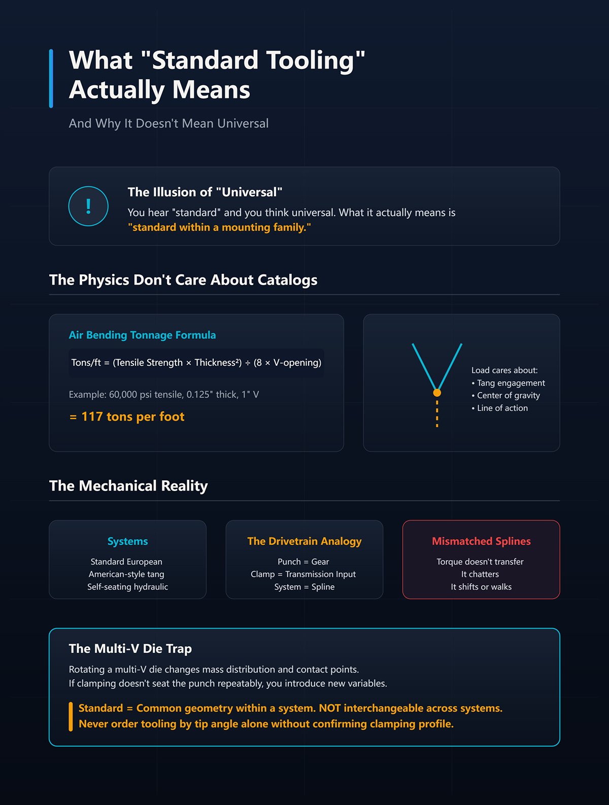
You hear “standard” and you think universal. What it actually means is “standard within a mounting family.”
Take a typical 60-ton air bend in mild steel. The tonnage formula for air bending is:
Tons/ft = (Material Tensile Strength × Thickness²) ÷ (8 × V-opening)
Run 60,000 psi tensile, 0.125″ thick, over a 1″ V:
(60,000 × 0.125²) ÷ (8 × 1) = (60,000 × 0.015625) ÷ 8 = 937.5 ÷ 8 = 117 tons per foot.
That load doesn’t care what catalog page your punch came from. It cares how the tang engages the clamp and where the center of gravity sits relative to the ram’s line of action.
“Standard European,” “American-style tang,” “self-seating hydraulic”—each is its own spline in a drivetrain. The punch is a gear. The clamp is the transmission input. If the splines don’t match, torque doesn’t transfer cleanly; it chatters, shifts, or walks.
A multi-V die looks versatile because you can rotate to different V openings. True. But rotate it and you change the die’s mass distribution and the contact point under load. If your clamping system doesn’t seat the punch repeatably across that rotation, your “standard” setup just introduced a new variable.
Standard means common geometry within a system. It does not mean interchangeable across systems. Never order tooling by tip angle alone without confirming the exact clamping profile and seating method on your machine.
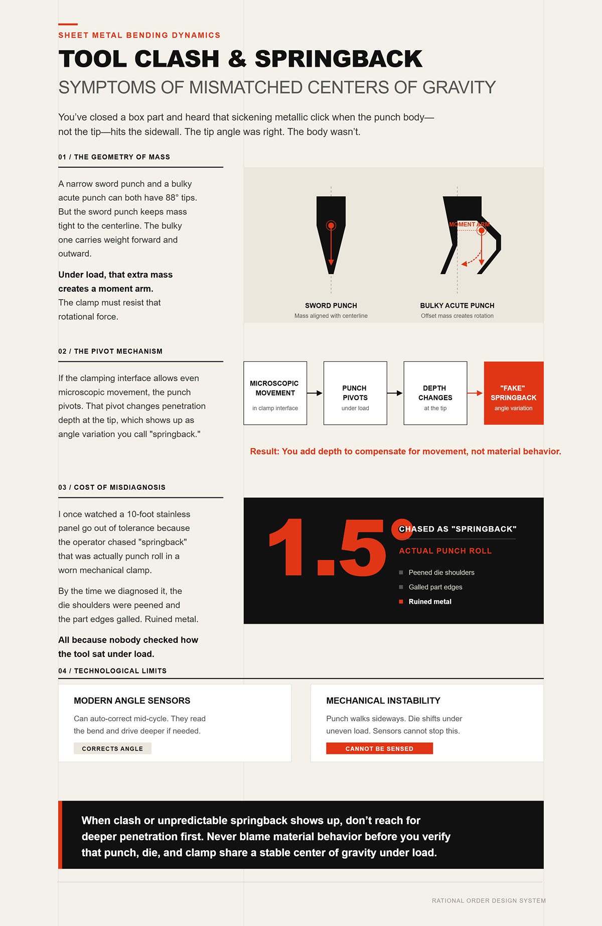
You’ve closed a box part and heard that sickening metallic click when the punch body—not the tip—hits the sidewall. The tip angle was right. The body wasn’t.
A narrow sword punch and a bulky acute punch can both have 88° tips. But the sword punch keeps mass tight to the centerline. The bulky one carries weight forward and outward. Under load, that extra mass creates a moment arm. The clamp must resist that rotational force.
If the clamping interface allows even microscopic movement, the punch pivots. That pivot changes penetration depth at the tip, which shows up as angle variation you call “springback.” So you add depth. Now you’re compensating for movement, not material behavior.
I once watched a 10-foot stainless panel go out of tolerance because the operator chased 1.5° of “springback” that was actually punch roll in a worn mechanical clamp. By the time we diagnosed it, the die shoulders were peened and the part edges galled. Ruined metal. All because nobody checked how the tool sat under load.
Modern angle sensors can auto-correct mid-cycle. They read the bend and drive deeper if needed. But they can’t stop a punch from walking sideways or a die from shifting under uneven load. Sensors correct angle. They don’t correct mechanical instability.
When clash or unpredictable springback shows up, don’t reach for deeper penetration first. Never blame material behavior before you verify that the punch, die, and clamp share a stable center of gravity under calculated tonnage.
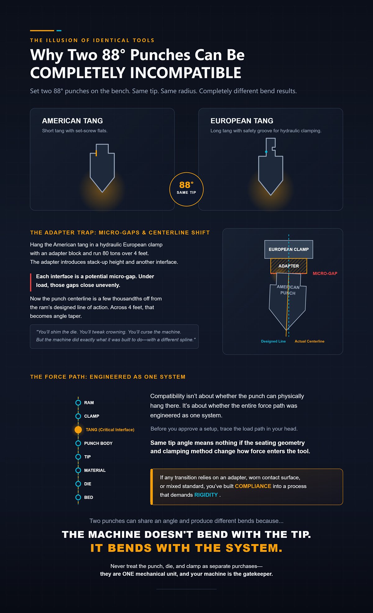
Set two 88° punches on the bench. One has a short American tang with set-screw flats. The other has a long European tang with a safety groove for hydraulic clamping. Same tip. Same radius.
Hang the American tang in a hydraulic European clamp with an adapter block and run 80 tons over 4 feet. The adapter introduces stack-up height and another interface. Each interface is a potential micro-gap. Under load, those gaps close unevenly.
Now the punch centerline is a few thousandths off from the ram’s designed line of action. Across 4 feet, that becomes angle taper. You’ll shim the die. You’ll tweak crowning. You’ll curse the machine.
But the machine did exactly what it was built to do—with a different spline.
Compatibility isn’t about whether the punch can physically hang there. It’s about whether the entire force path was engineered as one system. Same tip angle means nothing if the seating geometry and clamping method change how force enters the tool.
Before you approve a setup, trace the load path in your head: ram → clamp → tang → punch body → tip → material → die → bed. If any transition relies on an adapter, worn contact surface, or mixed standard, you’ve built compliance into a process that demands rigidity.
Two punches can share an angle and produce different bends because the machine doesn’t bend with the tip. It bends with the system. Never treat the punch, die, and clamp as separate purchases—they are one mechanical unit, and your machine is the gatekeeper.
You want to know how to verify compatibility before you run tonnage?
Here’s the first thing I do when I walk up to a machine: I don’t look at the punch tip. I look at the ram face and measure the clamping profile. Tang width. Tang depth. Presence of safety groove. Pin diameter if it’s a precision system. Then I check the manufacturer’s seating spec for that interface and compare it to the punch drawing. If those numbers don’t match within the intended mounting family, I stop right there.
Because your press brake does not accept “punches.” It accepts one exact mounting geometry. Everything else is a compromise, an adapter, or a guess.
And guessing is how metal gets ruined.
So let’s line them up the way they actually behave under load, not the way catalogs describe them.
Picture a classic American tang: short rectangular neck, two set screws pushing it against a rail. You slide it in, snug the screws, and it “feels” tight. Quick. Simple. Cheap.
Now put numbers to it.
Take that earlier 117 tons per foot example. Run just 3 feet of that bend and you’re pushing roughly 350 tons total distributed along the ram. The set screws don’t clamp vertically; they push laterally, forcing the tang against the rail face. Your vertical support comes from a narrow ledge under the tang.
So your force path is ram → rail → tang edge → punch.
That edge contact is small. Small contact area means higher contact stress. Over time, that rail face wears. Not catastrophically. Just a few thousandths.
A few thousandths at the rail becomes angular deviation at the tip because the tang can rock microscopically under load. That’s your hidden tolerance stack. You don’t see it until you start chasing depth adjustments.
I saw a shop running high-mix brackets on an older American-style clamp. Second hit: the flange came out 2° open. They blamed springback. Added depth. Third part over-bent. The real issue? The upper rail had worn unevenly where the heaviest punches always sat. The tang wasn’t seating flat anymore.
One chipped die shoulder later, they finally blued the tang and saw uneven contact.
The American system isn’t “bad.” It’s simple. But its accuracy depends on rail condition and set-screw discipline. It asks the operator to be part of the alignment system.
If you’re running low tonnage and infrequent changeovers, that may be perfectly adequate. If you’re cycling heavy tools all day, the rail becomes a consumable whether you budgeted for it or not.
Before running load on an American-style machine, remove the punch and inspect the rail face for galling or step wear, then blue the tang and verify full-length contact under light clamp pressure. Never assume a snug set screw equals full-surface seating.
Now look at a 20 mm precision tang with dual grooves and a pin-lock hydraulic clamp. You insert the punch, engage the hydraulic system, and the clamp pulls the tang upward into a machined reference surface. Vertical seating. Full-length support.
That system can hold roughly 45 kN of clamping force per station and remain stable at production stroke rates with punches up to about 110 pounds. That’s not marketing fluff. That’s engineered preload.
The difference is where the alignment responsibility lives.
In this system, the clamp defines the centerline. The tang geometry and the clamp’s hardened seating surfaces establish repeatability measured in microns. The operator’s job is just insertion and confirmation.
But here’s the part most people skip: now the clamp itself is a precision component. If hydraulic pressure drops, if pins wear, if debris sits in the groove, your “precision” system is no longer precise.
I’ve watched a shop retrofit hydraulic clamps onto a worn ram without checking straightness. Beautiful tooling. Crooked mounting surface. They expected the clamp to correct machine geometry.
It won’t.
These systems shine in high-mix, high-repeatability environments where tool changes are frequent and alignment must be automatic. But if you’re bending light-gauge mild steel once a week, the complexity may not earn its keep.
So how do you verify compatibility here?
Check tang dimension (20 mm means 20 mm, not 19.85 from a knockoff supplier), confirm groove position matches clamp spec, verify hydraulic pressure meets manufacturer requirement, and perform a seating test with feeler gauges across the tang length before loading tonnage.
Never assume “precision system” means self-correcting.
Now take a 13 mm European-style tang with a safety groove. The groove isn’t decorative. It’s there so the clamp lip can capture the punch even before full tightening, preventing drop-out.
What it actually means is “standard within a mounting family.”
The seating logic changes here. The clamp typically pushes the tang upward into a reference surface, similar in concept to precision systems, but often with manual tightening rather than hydraulic preload.
Your contact surfaces are broader than classic American rails, but the clamping force and repeatability depend on mechanical screw pressure and clean groove engagement.
Imagine debris packed in that safety groove. The clamp lip bottoms out on dirt before the tang fully seats. Under 80 tons, the tang shifts upward that last few thousandths.
You won’t see it until you measure taper across the part length.
I once saw a long acute punch eject slightly during a heavy stainless run because the groove lip had rounded from years of use. The punch didn’t fall. It just crept. The resulting angle variation scrapped an entire batch of enclosure panels.
The safety groove improves retention and alignment compared to a simple tang, but it introduces a new inspection point: groove integrity and clamp-lip condition.
Before loading production tonnage, inspect the safety groove for deformation, confirm clamp-lip engagement depth visually, and torque the clamp screws to spec rather than “hand tight.” Never ignore the groove as if it’s just a safety feature.
| System | Design Features | Force Path / Clamping Logic | Advantages | Hidden Risks / Tolerance Issues | Best Use Cases | Pre-Load Inspection Checklist |
|---|---|---|---|---|---|---|
| American-Style Tooling | Short rectangular tang; two lateral set screws; rail-based support | Ram → rail → tang edge → punch; lateral screw pressure forces tang against rail; vertical support from narrow ledge | Simple, quick, low cost; adequate for low tonnage | Small edge contact area increases stress; rail face wear causes angular deviation; tang can rock under load; operator-dependent alignment | Low tonnage jobs; infrequent tool changes | Inspect rail face for galling/step wear; blue the tang to verify full-length contact; confirm seating under light clamp pressure; do not rely solely on tight set screws |
| Wila / Trumpf Precision Systems | 20 mm precision tang; dual grooves; hydraulic pin-lock clamp; hardened reference surfaces | Hydraulic system pulls tang upward into machined reference surface; full-length vertical seating; engineered preload (~45 kN per station) | High repeatability (micron-level); automatic alignment; stable under production stroke rates; ideal for frequent changeovers | Clamp becomes precision variable; hydraulic pressure loss, pin wear, or debris affects accuracy; cannot compensate for worn or misaligned ram | High-mix, high-repeatability production; frequent tool changes | Verify exact tang dimensions (true 20 mm); confirm groove position per spec; check hydraulic pressure; perform feeler gauge seating test; inspect ram straightness |
| Promecam / European Style | 13 mm tang with safety groove; clamp lip captures groove; typically manual screw tightening | Clamp pushes tang upward into reference surface; retention via groove engagement; broader contact than American rail | Improved retention; safer insertion; better alignment than basic tang systems | Debris in groove prevents full seating; clamp lip wear allows punch creep; screw torque affects repeatability; upward shift under heavy load | Moderate to heavy production with standardized mounting families | Inspect safety groove for deformation/debris; check clamp-lip condition and engagement depth; torque screws to specification; confirm full seating before tonnage |
Now we get to the quiet killer.
You’ve got a European clamp machine. You own a pile of American punches. So you buy adapter blocks. Problem solved, right?
Let’s trace the force path.
Ram → hydraulic clamp → adapter → American tang → punch body → tip.
Every added interface is another potential compliance layer. If any interface in that chain doesn’t lock the centerline exactly where the designer intended, the force vector shifts.
CNC crowning assumes a known tool height and rigidity. Add an adapter that changes stack height by even 0.500″. Your deflection model is off. Add slight lateral clearance between tang and adapter. Now you have rotational freedom under load.
The machine still cycles perfectly. The angle sensor still reads correctly. But the punch can move microscopically before the sensor reacts.
I’ve seen a 10-foot panel show inconsistent angles across stations because mixed adapters seated differently along the ram. The operator chased the issue with crowning adjustments for hours. The real fix was removing the adapters and standardizing the mounting family.
Adapters are sometimes unavoidable during transition periods. Fine. But treat them as engineered components, not convenience blocks.
Measure adapter thickness at multiple points. Confirm parallelism. Verify tang fit with no lateral play before clamping. Recalculate tool stack height in the CNC control rather than assuming equivalence.
Never mix mounting systems on a precision job without revalidating the entire force path from ram to bed.
You verify compatibility by measuring geometry, confirming seating mechanics, inspecting wear surfaces, and tracing the load path before the first stroke. Once the mounting family is locked in and mechanically sound, only then does it make sense to talk about punch geometry and material behavior.
Because once the spline matches the transmission, you can finally choose the right gear.
And that’s where the real bending decisions begin.
You’ve verified the tang, the clamp, the seating surfaces. The drivetrain spline matches. Good.
Now you’re staring at the rack, thinking, 90° bend… so I’ll grab a 90° punch.
That’s backwards.
Start with a real job. Say 3 mm 304 stainless, air bending, target inside radius around 3 mm, 40 mm flange. If you follow the lazy rule—V = 8T—you’d pick a 24 mm die. But stainless isn’t mild steel. It work-hardens fast and cracks if you choke it. In practice you open that die to 10T or even 12T. Call it 30–36 mm.
And here’s the part most guys miss: once that V-opening moves, the internal radius in air bending moves with it. The punch nose didn’t set the radius. The material strength and die opening did.
Punch geometry is downstream of thickness, alloy, flange length, and method. The formula does not care what you have on the rack.
Never pick a punch by angle before you calculate the material window it must live inside.
I once watched a shop bend 2 mm 5052 with a 0.2 mm nose radius punch because “it makes crisp corners.” First batch looked fine. Second batch? Hairline fractures along the bend line after powder coat. The parts passed visual. They failed in service.
Here’s the mechanism.
In bottoming or coining, the punch nose radius becomes the inside bend radius. So minimum punch nose radius must respect minimum inside radius for the alloy. For many aluminums, that’s roughly 1T for tight bends; for harder tempers, more. If T = 2 mm and you coin with a 0.2 mm nose, you’re forcing an Ri = 0.2 mm into material that wants 2 mm. The strain exceeds elongation. It cracks. Simple math.
In air bending, it shifts. The inside radius approximates V/6 to V/8 depending on material strength. If you choose V = 8T on 2 mm mild steel, that’s 16 mm. Ri lands around 2–2.7 mm. Change the material to stainless and open to V = 12T (24 mm). Now Ri grows toward 3–4 mm. Same punch. Different radius. Because method and die dominate.
And tonnage follows the same logic. Air bending force per foot is roughly:
Tons/ft = (575 × T²) / V (for mild steel)
Plug in 3 mm (0.118 in) and V = 1 in equivalent, you get a specific load. Open V wider and required tonnage drops. Bottoming? Multiply air-bend tonnage by 3 to 5. Coining? Up to 8 to 10 times. Your punch must survive that. Thin acute punches under coining loads fold like soda cans.
So the correct nose radius is not preference. It’s bounded by:
If you haven’t written those three down, you’re guessing.
Never choose a punch nose radius smaller than the material’s allowable inside radius for the bending method you’re actually using.
Picture a channel: 2.5 mm mild steel, 20 mm side flanges, then a 15 mm return flange inward at 90°. You can calculate V all day. It won’t matter if the punch body crashes into the vertical wall before the tip reaches depth.
This is where “clearance-required” stops being a catalog phrase and becomes geometry.
A straight punch has a body width above the tip. During the second hit, that body swings into the previously formed flange. If the flange height is less than the punch’s daylight clearance, you physically cannot complete the bend. The flange dimension has now dictated punch style.
Gooseneck punches neck inward above the tip to create clearance for return flanges. But that neck reduces cross-sectional stiffness. Under higher loads—say 6 mm plate, bottoming—the deflection increases. Angle variation creeps in across long lengths.
Now tie it back to force. If your 2.5 mm mild steel runs air bend with V = 8T (20 mm), tons/ft ≈ (575 × T²) / V. Convert 2.5 mm to inches (0.098 in). Square it, multiply, divide—you’ll land in a manageable range. A gooseneck survives comfortably. Try that geometry in 6 mm stainless, bottoming at 4× air tonnage. That same neck becomes a hinge.
So flange length and return geometry choose between straight and gooseneck before angle enters the conversation. And material thickness decides whether that gooseneck is structurally sane.
I’ve seen a tall return flange job run on a straight punch “because it was already set up.” Second hit: the flange came out 2° open along the center because the operator feathered depth to avoid collision. They didn’t solve geometry. They tiptoed around it.
Never ignore flange interference when selecting punch style—draw the bend sequence full-scale and check physical clearance before you even calculate V.
Take sheet under 3 mm. Acute punches—those sharp included angles—reduce required penetration in air bending. Less penetration means less contact area, less required force. For thin material, that’s an advantage. You get cleaner bends with lower tonnage demand.
Move above 3 mm. Now rigidity matters more than tip sharpness. Straight punches with larger included angles and thicker bodies resist deflection. Especially if you bottom.
Here’s the dividing line most shops blur:
If you air bend 2 mm mild steel at V = 16 mm, tons/ft ≈ (575 × T²) / V. Open the V to 20 mm, tonnage drops further. An acute punch thrives here. Try bottoming that same setup and multiply the force. Suddenly your slender acute punch is carrying loads it wasn’t built for.
The bending method is not an afterthought. It determines whether the punch geometry is shaping the radius or merely participating in a three-body interaction between punch, die, and material.
So the hierarchy is strict:
Machine interface locks the centerline. Material thickness and alloy define allowable strain and die window. Flange geometry dictates punch style. Bending method sets how much the punch actually controls the radius—and how much load it must survive.
Only inside that narrow window does “90° or 88° punch?” become a meaningful question.
Never select punch geometry without first stating—out loud—the material, thickness, flange constraints, die opening calculation, and bending method in one sentence.
You want a step‑by‑step process for selecting the correct punch.
Good. Then stop staring at the punch rack and look down at the die.
Start with a real job: 3 mm mild steel, air bend, 90°, 1 meter long. You already know the air‑bend formula:
Tons/ft = (575 × T²) / V (mild steel)
Convert 3 mm to 0.118 in. Square it: 0.0139. Multiply by 575: about 8.0. Now divide by V. If you choose a 1.0 in V‑opening (about 8.5× thickness), you’re at roughly 8 tons per foot. Open the V to 1.25 in, tonnage drops to about 6.4 tons per foot. Same material. Same angle. Different die.
That V also sets your inside radius in air bending—roughly V/6 to V/8 depending on strength. So 1.0 in V gives you about 0.125–0.167 in radius. Open to 1.25 in and your radius grows with it.
You haven’t touched the punch yet, and already the radius and load have moved.
This is why die selection comes first. V‑opening is not a guess; it is the multiplier that defines both strain and force. Change it and you change springback, tonnage, and whether the punch you liked on paper survives the job.
Never pick a punch before you calculate V‑opening and resulting tons per foot on the actual material.
I’ve watched a shop bend 2 mm stainless on a 16 mm V because “8× is standard.” Parts came off 1.5° open. They chased it with depth. Overbent. Inconsistent along the length. The die wasn’t wrong by catalog logic. It was wrong for the alloy.
The “8× rule” is an average, not a law. For mild steel under 4 mm, 5–6× thickness is often more stable. Stainless over 4 mm may demand 6–8×. Aluminum at 4 mm and up can push 8–10× to avoid cracking. Those multipliers shift because yield strength and elongation shift.
Mechanism matters. Narrower V increases penetration for a given angle, increasing plastic strain through the thickness. More plastic strain means less elastic recovery—less springback. Open the V too far and you reduce strain; elastic recovery dominates; the part springs open. You cannot “compensate” that with punch angle because the die controls the bend arc in air forming.
And tonnage moves the opposite direction. Using the same formula, halve the V and you double the tons per foot. That extra load has to travel through the clamping spline, through the punch body, into the die shoulders. If any interface in that chain doesn’t lock the centerline exactly where the designer intended, the force vector shifts.
I once saw 4 mm 304 run on a 12× V to “reduce tonnage.” Springback went wild, operators cranked depth, and the die shoulders polished a bright witness line into every part. The metal wasn’t wrong. The multiplier was.
Never quote “8× thickness” without naming the material, thickness range, and calculated tons per foot in the same breath.
Picture a 4‑way die block: 16 mm, 22 mm, 30 mm, 40 mm openings. Convenient. Flip and go.
Now clamp it slightly off center in a system that’s worn 0.05 mm on one side of the rail. On a single‑V die, the centerline error is small and predictable. On a multi‑V, each groove sits at a different lateral position relative to the clamping faces. Flip the block and you’ve changed not just V, but the load path across the bed.
Run the numbers. Suppose 3 mm mild steel on a 22 mm V (about 7.3×). In metric form, the air‑bend load approximation is:
kN/m ≈ (1.42 × Rm × T²) / V
Assume tensile strength around 450 MPa. Plug it in and you’re in the neighborhood of 100 kN/m. That force must sit symmetrically over the ram and bed. Shift it a millimeter off true center because the die block’s geometry and clamp faces aren’t perfectly matched, and you introduce uneven shoulder loading.
The part shows it as angle variation side to side. The operator blames crowning. The real culprit is that the “versatile” die changed the drivetrain geometry.
I’ve seen a long aluminum panel scrapped because a multi‑V die was flipped mid‑run after a tool change. Same nominal V. Different groove position. The load line moved. The panel cambered.
Versatility is fine for job shops. Precision work demands repeatable centerline geometry between die groove and clamping interface.
Never treat multi‑V dies as geometrically identical to single‑V dies without verifying groove centerline relative to the machine’s datum.
Take 2 mm 5052 aluminum, cosmetic face out. Run it over a sharp‑edged die shoulder with a small radius. You’ll get a bright pressure line exactly at the tangent point where the sheet transitions into the V. That’s not cosmetic bad luck. It’s contact mechanics.
As the punch drives material into the die, contact pressure concentrates along the die shoulders. A small shoulder radius increases contact stress. High stress plus soft aluminum equals galling and visible marking. Increase the shoulder radius and you spread the load over a wider area, lowering peak pressure. Surface finish does the same—polished shoulders reduce friction, lowering drag marks during sliding.
But change that shoulder radius and you subtly change how the material flows into the V. On very tight V‑openings, a large shoulder radius effectively narrows the working opening at initial contact, increasing early resistance and altering bend progression. It feeds back into tonnage and springback behavior.
This is why you cannot isolate “marking” as a cosmetic issue. The die shoulder radius and finish influence friction coefficient, which influences force distribution, which influences angle consistency across the length.
I once watched decorative stainless parts ruined because a die with worn, rough shoulders was “close enough.” The finish transferred as a faint serration across every bend line. The metal remembered every scratch in that die.
Never ignore die shoulder radius and surface condition when surface finish or tight angle tolerance is specified—inspect and measure them before the first hit.
You asked for a step‑by‑step process. Here it is in order:
That’s the drivetrain engaged correctly. The next question is whether the tooling itself is strong enough to survive the loads you just calculated.
You ran the formula. You picked the V-opening. You verified alignment.
Now the real question: will the punch survive what you just asked it to do?
A press brake can be rated for 300 tons, 600 tons, 1,000 tons. That number means the frame can push that hard across the bed. It says nothing about the thin line of steel at the punch tip taking the load per foot. The machine is the engine block. The punch tip is the connecting rod. Confuse the two and something small fails first.
Power doesn’t transfer safely just because the gears mesh.
Start with the air-bend formula you already used:
kN/m ≈ (1.42 × Rm × T²) / V
Then add 20 percent. Not as a guess — as insurance for friction, real tensile variation, and the fact that your sheet isn’t lab-perfect.
Now convert that to tons per foot and compare it to two numbers: the machine’s rated tons per foot at that bend length, and the punch’s rated tons per foot from the manufacturer. They are not interchangeable.
Here’s where apprentices get hurt by math they think they understand. Thickness is squared. Double T and the load jumps fourfold. That prototype in 3 mm mild steel ran fine at 8 tons per foot. Production switches to 6 mm. You didn’t double the load. You quadrupled it. The press might still be within its global rating — especially on a short part — but the punch tip may not be.
I watched an acute punch mushroom on stainless because the operator trusted the machine’s 220-ton badge more than the punch’s 18 tons-per-foot limit. First hit looked fine. Second hit: the flange came out 2° open. By the fifth, the tip had spread just enough to change the effective nose radius and the angle drifted across the batch. The machine never complained. The tool absorbed the lesson.
Never assume machine tonnage equals punch capacity — calculate tons per foot with the formula, add 20 percent, and verify against the punch’s published rating before the first cycle.
Load is one failure mode. Wear is the other.
Non-hardened tooling might sit around 28–32 HRC. Hardened tools push into the high 40s or low 50s. That difference decides whether abrasive scale, laser oxide, or stainless chromium turns your precision edge into a file.
Air bending mild steel on clean stock? Non-hardened may live a long, honest life. Start running pickled-and-oiled with embedded grit, or stainless with higher tensile strength and work-hardening behavior, and the contact pressure at the punch nose becomes a grinding operation under load.
It happens slowly. Then all at once.
I saw a set of non-hardened punches used on abrasive 304 with heavy mill scale. After a few thousand hits, the nose radius had worn unevenly along the length. The operator chased angle with depth adjustments. The parts showed faint tracking lines and inconsistent springback. By the time anyone measured the nose, it was out of spec by tenths of a millimeter — enough to shift strain distribution and effective tonnage. The metal wasn’t wrong. The surface hardness was.
What it actually means is “standard within a mounting family” — not “indestructible across materials.”
Never run abrasive or high-tensile material on non-hardened tooling without calculating contact load and confirming the hardness is appropriate for the material class.
You think you’re changing material. You’re really changing the force curve.
Take the same thickness and V-opening. Mild steel at 450 MPa tensile versus stainless at 650 MPa is not a subtle shift. Plug that into the same air-bend equation and the load scales directly with tensile strength. That 8 tons per foot becomes 11 or 12 before you add your 20 percent margin.
And stainless springs back more. So you close the angle with additional penetration. More penetration increases contact pressure at the nose and die shoulders. Which increases localized stress on the punch tip. Which eats into your safety margin.
The machine might still be within rating. The punch may not be.
On a long bend, the problem compounds. Even if total tonnage is acceptable, any slight mismatch in clamping rigidity changes how that higher load distributes along the length. If any interface in that chain doesn’t lock the centerline exactly where the designer intended, the force vector shifts — and stainless will magnify that shift because it resists plastic deformation longer before yielding.
Mild steel forgives. Stainless reports you.
Never switch from mild steel to stainless without recalculating tons per foot using actual tensile values, adding 20 percent capacity, and confirming both punch rating and clamping rigidity can carry the new load.
You’ve now seen the pattern: geometry defines force, force tests capacity, material amplifies everything. The next step isn’t another caution — it’s building a repeatable decision sequence that locks clamping, geometry, tonnage, and hardness together before you ever touch the pedal.
You want a sequence that forces clamping, geometry, tonnage, and hardness to agree before the first hit.
Good. Because the only way this stops being guesswork is if you spec tooling the same way a machinist specs a shaft: one interface at a time, in the order force actually travels.
Force doesn’t start at the angle. It starts at the ram, passes through the clamp, into the punch, across the sheet, into the die, and back into the bed. If any interface in that chain doesn’t lock the centerline exactly where the designer intended, the force vector shifts. And once it shifts, your calculations become fiction.
So we’re going to spec in the order the load flows.
Transmission spline first. Gears second. Horsepower last.
Anything else is how good steel turns into scrap.
I once watched a shop swap to a “universal” punch on a different brake because the angle matched. It seated. It bent. It also sat 0.4 mm off centerline because the tang geometry didn’t match the clamp family. After a week of chasing taper, they found fretting marks on the rail and a slight polish on one shoulder of every die.
The tooling wasn’t wrong. The interface was.
Quick-change, European style, American style, proprietary front-loading—these are not cosmetic differences. They define:
What it actually means is “standard within a mounting family.” Not across families.
You don’t choose punches until you answer three machine questions:
If the clamp is rated for 20 tons/ft and your calculation (with the 20 percent margin) says 24, it doesn’t matter how beautiful the punch is.
Lock the mounting family first. Everything else must fit that spline.
Never evaluate punch profiles or die options before confirming clamping compatibility, centering method, and tons‑per‑foot rating of the interface.
Angle does not dictate punch angle in air bending. Penetration depth does. The punch is a force applicator; the die opening controls the load.
Start with the part print:
Then calculate your V-opening. For air bending mild steel, you might begin around 6–8 × T. But that’s a starting range, not a decision.
Use the formula:
kN/m ≈ (1.42 × Rm × T²) / V
Solve for V based on allowable tons per foot from Step 1.
If the required V to stay under clamp and punch capacity produces an inside radius larger than the print allows, you don’t “adjust depth.” You either change tooling style or challenge the print.
Now the edge case apprentices miss: if the center web of a channel is narrower than roughly half the die body width, the part can’t straddle the die properly in standard air bending. You’re into form tools or special dies, often at multiples of the original force. That’s not an angle problem. That’s geometry overriding your workflow.
I saw a narrow return flange forced over a standard die because “the V matched the thickness.” The web bottomed on the die shoulders before the bend completed. The operator increased depth. The punch nose brinnelled, and the part cambered along its length.
Geometry spoke first. The operator didn’t listen.
Never select a punch by included angle alone — calculate the V-opening from tensile strength and thickness, confirm it satisfies radius and flange constraints, and verify the die body width actually supports the part geometry.
Now we check whether the machine can physically execute what the math demands.
Shut height is the total stack: ram to bed at bottom dead center minus tooling height. If your punch and die combination exceeds the machine’s daylight or stroke, you won’t discover it in CAD. You’ll discover it when the ram alarms halfway down.
Then tonnage per foot:
Compare that number to:
All three must exceed your required value.
And length matters beyond force. Long bends introduce ram deflection. If the machine lacks adequate crowning adjustment, your calculated load will concentrate toward the center. The math assumed uniform distribution. The steel will not.
I watched a 10-foot stainless panel run on a brake without active crowning. The ends were perfect. The center was 1.5° open. The operator compensated with depth. The next short part over-bent in the middle because the compensation stayed. The tool tips showed uneven polish within days.
Capacity isn’t just “can it push.” It’s “can it push evenly.”
Never approve a tooling stack until shut height fits within machine stroke, required tons per foot (with margin) are below machine, punch, and clamp ratings, and crowning capability matches the planned bend length.
Here’s the lens I want you to carry back to the machine.
Stop thinking in angles. Start thinking in load paths.
The clamp is the spline. The punch and die are the gears. The material is the resistance. The machine rating is just the engine block. If the spline doesn’t match, no amount of horsepower or angle correction transfers force cleanly.
So the order is fixed:
That sequence feels non-obvious because most operators start with the visible thing — the bend angle. But angle is the final expression of a force chain that began at the clamp.
When you treat tooling as a part, you chase defects.
When you treat it as a system, you predict them before they happen.
Never order press brake tooling until you can trace the entire force path — clamp to punch to material to die to bed — and prove, with numbers, that every interface in that chain is compatible.


