

Last month I watched a new operator fight a punch for twenty minutes because the salesman told him, “That’s American style — it’ll fit.” The tang slid in. The bolts tightened. The ram came down.
The part still crowned in the middle and opened at the ends.
He kept blaming the program. I kept watching the tool shift under load. What do you think the machine actually cares about?
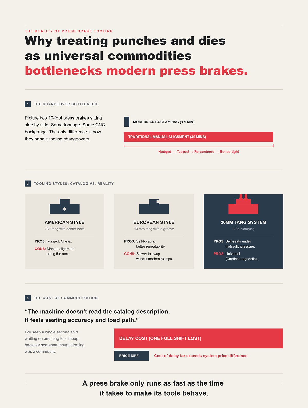
Picture two 10-foot press brakes sitting side by side. Same tonnage. Same CNC backgauge. One swaps tools in under a minute; the other eats half an hour every changeover because the punch has to be nudged, tapped, re-centered, and bolted tight along the beam.
Both are labeled by “region.”
American-style tang with center bolts? Rugged. Cheap. Popular half-inch tang. But every section has to be manually aligned along the ram. European-style 13 mm tang with a groove? More self-locating, better repeatability, but slower to swap unless the clamp system is modern. Then you’ve got 20 mm tang systems with auto-clamping that self-seat under hydraulic pressure — they don’t care what continent you’re on.
The machine doesn’t read the catalog description. It feels seating accuracy and load path.
Call it American. Call it European. If the clamping surface is narrow and the seating depends on how square you tightened a bolt, your “style” just became a bottleneck. I’ve seen a whole second shift waiting on one long tool lineup because someone thought tooling was a commodity — that delay cost more than the price difference between systems.
And here’s the reality check: a press brake only runs as fast as the time it takes to make its tools behave.
Let’s talk about “close enough.”
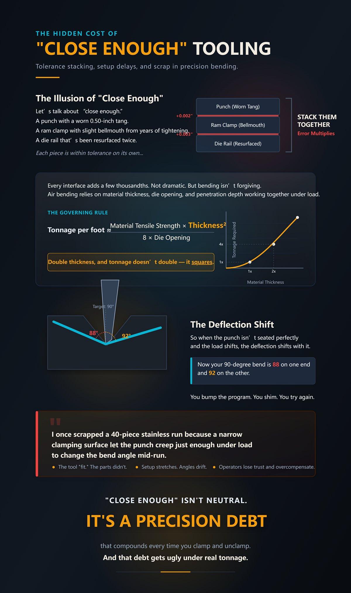
A punch with a worn 0.50-inch tang. A ram clamp with slight bellmouth from years of tightening. A die rail that’s been resurfaced twice. Each piece is within tolerance on its own.
Stack them together.
Every interface adds a few thousandths. Not dramatic. But bending isn’t forgiving. Air bending relies on material thickness, die opening, and penetration depth working together under load — and force climbs fast. The old rule you learned still holds: Tonnage per foot ≈ (Material Tensile Strength × Thickness²) ÷ (8 × Die Opening). Double thickness, and tonnage doesn’t double — it squares.
So when the punch isn’t seated perfectly and the load shifts, the deflection shifts with it. Now your 90-degree bend is 88 on one end and 92 on the other. You bump the program. You shim. You try again.
I once scrapped a 40-piece stainless run because a narrow clamping surface let the punch creep just enough under load to change the bend angle mid-run. The tool “fit.” The parts didn’t.
Setup stretches. Angles drift. Operators lose trust in the machine and start overcompensating.
“Close enough” isn’t neutral. It’s a precision debt that compounds every time you clamp and unclamp.
And that debt gets ugly under real tonnage.
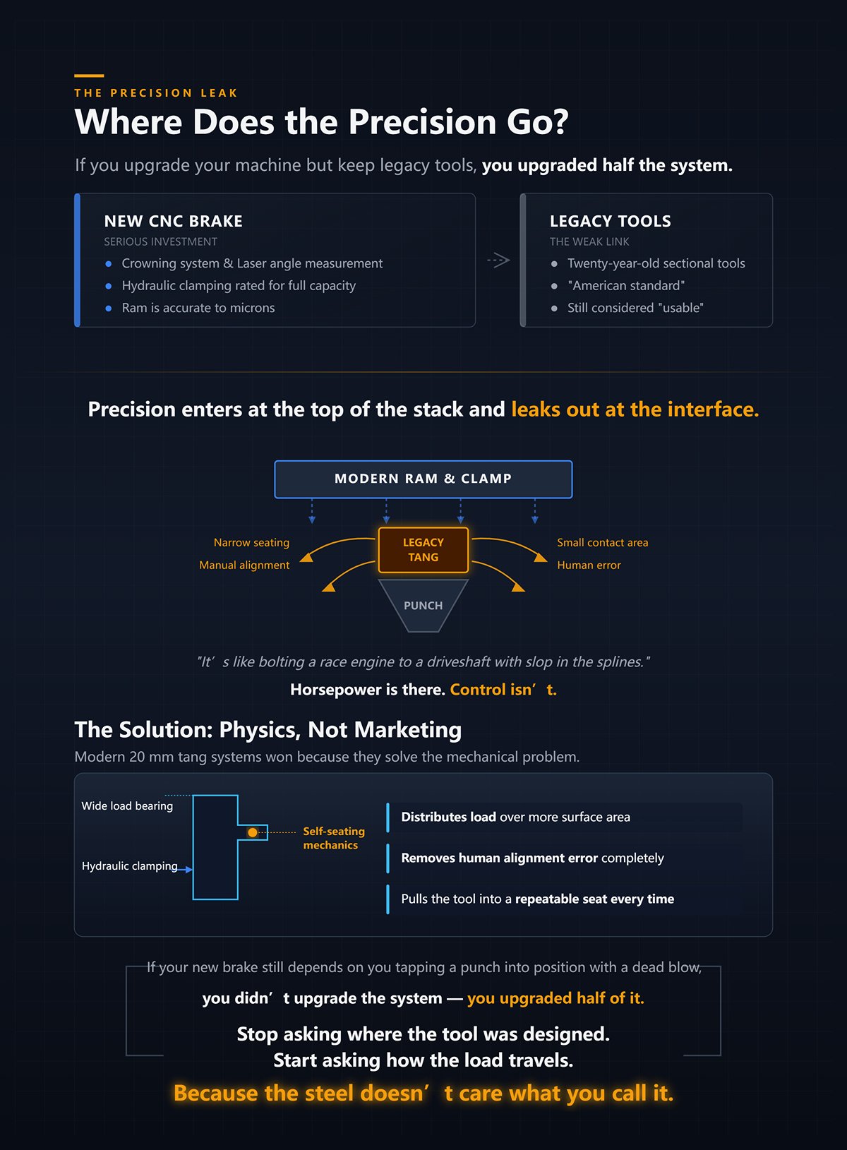
You drop serious money on a new CNC brake. Crowning system. Laser angle measurement. Hydraulic clamping rated for full capacity.
Then you slide in twenty-year-old sectional tools because they’re “American standard” and still usable.
The ram is accurate to microns. The clamp applies even pressure. But the tang geometry is still what it was — narrow seating, manual alignment, small contact area. Precision enters at the top of the stack and leaks out at the interface.
It’s like bolting a race engine to a driveshaft with slop in the splines. Horsepower is there. Control isn’t.
Modern 20 mm tang systems with self-seating mechanics didn’t become common because of geography. They won because they distribute load over more surface area and remove human alignment error. Spring buttons for light tools. Pins for heavy ones. Hydraulic clamping that pulls the tool into a repeatable seat every time. That’s physics solving a problem, not marketing solving a naming convention.
If your new brake still depends on you tapping a punch into position with a dead blow, you didn’t upgrade the system — you upgraded half of it.
And here’s the shift I need you to make: stop asking where the tool was designed, and start asking how the load travels from ram to punch to material to die.
Because the steel doesn’t care what you call it.
You’re standing in front of a spec sheet. It says American. It says European. It says Wila-compatible.
You want to know: what measurements actually tell me if this will bend straight parts all day without babysitting?
Start with three numbers: tang thickness, seating surface width, and rated load per foot. Then look at how the clamp pulls the tool into position — bolt pressure, wedge action, hydraulic draw-in. That’s the load path. That’s the repeatability.
Choosing by region is like buying an engine by the color of the valve cover. The badge is cosmetic. The torque curve is mechanical.
Let’s break down the four systems the way the steel feels them — by how they seat, how they carry tonnage, and how they behave after the hundredth tool change.
I’ve set miles of 0.50-inch tang tooling in my life. Slide the tang into the slot. Snug the center bolt. Tap the section with a dead blow until it lines up with its neighbor. Move down the beam. Repeat.
It works. That’s why it’s still everywhere.
But look at the interface. A half-inch tang. Narrow bearing surface. Alignment handled by the operator’s eye and elbow grease. The clamp pushes straight in; it doesn’t self-center. Every tool change is a small negotiation between steel and human judgment.
Now compare planed versus precision-ground American tooling. Planed tools are machined to size but not finish-ground across the full length. You’ll see slight variation from section to section — a couple thousandths here, a couple there. On a short part, you might never notice. On a 10-foot run, those thousandths stack.
Precision-ground American tooling tightens that variation. Better surface finish. Straighter sections. More consistent height across the beam.
But the tang geometry didn’t change.
Under load, the clamp is still squeezing a relatively small contact area. When tonnage climbs — thicker material, narrower V-die — deflection concentrates at that interface. If the seating isn’t perfectly square, the punch can micro-shift before the full load settles.
I once watched a cracked die come off a brake because the punch wasn’t fully seated at one end. Heavy plate, near capacity. The load walked to the high side, over-stressed the shoulder of the die, and split it clean. The tooling wasn’t “wrong.” The interface was unforgiving.
So when does the workhorse become a liability? When your part length magnifies section-to-section variation, when your tonnage approaches the upper range, or when you’re swapping tools multiple times per shift and expecting microns of repeatability from a system that depends on manual alignment.
American tooling isn’t obsolete. It’s honest. It gives you exactly the precision your setup discipline earns.
Push it beyond that, and it charges interest.
Now take a 13 mm tang with a rear groove. Slide it into a matching clamp. As the clamp closes, it pulls the tool up and back into a defined seat. You don’t tap it into alignment — the geometry does that for you.
That’s the Promecam-style advantage: mechanical self-location.
Changeover time drops because alignment time drops. More important, the seating repeatability improves because the clamp applies force along an angled surface that drives the tool into position the same way every cycle.
Here’s the trade-off.
That tang is slimmer than a 20 mm heavy-duty system. The contact area is smaller. The system is typically rated for lighter to medium tonnage work unless paired with reinforced holders. You can absolutely run serious work on it — but you must respect the load chart.
And remember something about air bending: the inside radius is governed primarily by the die opening, not the punch profile. If you’re air bending mild steel at 1T punch radius — tip radius about equal to material thickness — your angle consistency depends more on consistent penetration depth and die width than on exotic punch shapes.
So what do you think the machine actually cares about?
It cares that the punch seats the same way every time so penetration depth translates into predictable angle. The self-centering geometry helps that. But if you overload the tang beyond its rated tonnage per foot, the self-centering feature won’t save you from elastic deformation in the holder.
European style shines in high-mix, moderate-tonnage environments where repeatable alignment and quick swaps outweigh brute capacity. Ignore the weight limits, and you’re asking a slim interface to behave like a heavy one.
Steel doesn’t negotiate with your schedule.
The first time you use a 20 mm tang with hydraulic clamping, it feels different. You lift the tool. It engages. The clamp closes. The system pulls the tool into a hardened reference surface across a broad contact area.
No tapping. No shimming. No guesswork.
Light sections often use spring-loaded buttons for quick placement; heavier sections switch to a pin-locking mechanism. Same geometry, different retention method depending on weight. That detail matters — because the speed advantage is greatest when you’re handling lighter, sectional tooling repeatedly.
Mechanically, the 20 mm tang increases the bearing surface between tool and ram. More surface area means lower contact stress for the same load. Under high tonnage per foot, that translates into less localized deformation and better long-term repeatability.
So does the setup speed offset the price?
If you’re changing tools once a day, probably not. If you’re running short batches — say five to ten setups per shift — and each traditional manual alignment eats fifteen minutes, you’re burning over an hour daily just persuading tools to behave.
And here’s the reality check: a press brake only runs as fast as the time it takes to make its tools behave.
The premium isn’t about geography. It’s about buying back setup time and protecting interface precision under load. For mid-volume, high-mix shops, the math often tilts toward the broader tang and hydraulic draw-in. For long-run, stable jobs, the gain shrinks.
Speed only pays when you actually change things.
I’ve seen shops order premium self-seating tooling — then bolt it into an old manual clamp designed for a straight 0.50-inch tang. They made it “fit” with adapters.
Adapters change the load path.
A manual clamp applies point pressure where the bolt sits. A hydraulic clamp distributes force evenly along the beam. Pneumatic systems sit in between — faster than manual, typically less force than hydraulic.
If your machine has manual clamping, every tool change reintroduces human alignment error, no matter how fancy the tang geometry is downstream. If it has hydraulic clamping rated for full tonnage, running narrow, lightly supported tooling leaves capacity on the table and increases interface stress.
Your clamping system decides what tooling you can safely and repeatably run long before your budget gets a vote.
I once scrapped a rush aluminum job because an adapter stack introduced just enough flex that angle readings drifted partway through the run. We chased the program for an hour before tracing it back to the clamp interface. The tooling catalog looked compatible. The load path wasn’t.
Manual clamps favor robust, forgiving geometries. Hydraulic clamps unlock precision systems that depend on consistent draw-in force. Pneumatic systems demand you check both speed and force ratings before assuming interchangeability.
This is where the regional labels fall apart completely.
The question isn’t American or European. It’s: how is the tool pulled into its seat, over how much surface area, and at what tonnage per foot?
Answer that, and half the buying mistakes disappear.
Ignore it, and you’ll keep blaming the CNC for what the interface is doing in plain sight.
| Section | Content |
|---|---|
| Title | Manual vs. Hydraulic vs. Pneumatic Clamping: How your machine’s clamping system instantly disqualifies entire tooling categories |
| Core Observation | Shops often order premium self-seating tooling and install it into old manual clamps designed for a straight 0.50-inch tang, using adapters to make it fit. |
| Key Principle | Adapters change the load path. |
| Manual Clamping | Applies point pressure where the bolt sits. Reintroduces human alignment error with every tool change, regardless of tang geometry. Favors robust, forgiving geometries. |
| Hydraulic Clamping | Distributes force evenly along the beam. When rated for full tonnage, running narrow or lightly supported tooling wastes capacity and increases interface stress. Unlocks precision systems that depend on consistent draw-in force. |
| Pneumatic Clamping | Sits between manual and hydraulic systems. Faster than manual, typically less force than hydraulic. Requires verification of both speed and force ratings before assuming interchangeability. |
| Practical Insight | The clamping system determines what tooling can be run safely and repeatably before budget considerations. |
| Real-World Example | An aluminum rush job was scrapped because an adapter stack introduced flex, causing angle drift mid-run. The issue traced back to the clamp interface, not the program. The tooling catalog appeared compatible, but the load path was not. |
| Critical Question | Not American vs. European tooling — but how the tool is pulled into its seat, over how much surface area, and at what tonnage per foot. |
| Conclusion | Answering these interface questions prevents many purchasing mistakes. Ignoring them leads to blaming the CNC for issues caused by the clamping interface. |
Picture this: 0.125-inch mild steel, 10 feet long, 90-degree bend. You’ve got a 175-ton hydraulic brake. The die rack offers a 0.75-inch V and a 1.0-inch V.
Which one keeps you out of trouble?
Start with the Rule of 8: V = 8 × T. For 0.125-inch material, that’s a 1.0-inch V. Not because Europe said so. Not because America prefers something beefier. Because at eight times thickness, the material can form a predictable inside radius—about 0.16 inch in mild steel—and the tonnage per foot stays in the range your machine and tooling were designed to carry.
That multiplier isn’t folklore. It’s the hinge between geometry and force. Deviate from it, and the load path changes in ways your ram, your die shoulders, and your clamp will absolutely notice.
Steel doesn’t negotiate with your schedule.
Let’s run the numbers instead of arguing brand names.
For air bending mild steel at 60,000 PSI tensile strength, tonnage per foot is roughly proportional to T² / V. Cut the V opening in half and you nearly double the required tonnage. Same material. Same thickness. Just a narrower V.
So if your 0.125-inch sheet goes from a 1.0-inch V to a 0.75-inch V because “we need a tighter radius,” your tonnage per foot jumps hard. Not politely. Hard.
Now scale that across 10 feet.
On a synchronized downstroke hydraulic press, that extra demand shows up as higher hydraulic pressure, more ram deflection at mid-span, and greater concentrated load at the die shoulders. The frame doesn’t care what the tooling catalog called the die. It cares about bending moment.
What do you think the machine actually cares about?
It cares that the force curve stays inside its rated capacity—both total tonnage and tonnage per foot. Electric brakes are even less forgiving; they often cap peak force lower than comparable hydraulic machines. A die choice that’s “fine” on a 200-ton hydraulic unit can stall an electric drive at the bottom of stroke.
And if you switch from air bending to bottoming mid-job without recalculating?
Bottoming can demand 3–5× the tonnage of air bending because the material is forced into full contact with the die flanks. That contact multiplies resistance. I’ve seen a crew run a job safely in air bend, then bottom the last flange “to sharpen it up.” The die cracked along the shoulder radius. One sharp report. Job over.
Here’s your blunt reality: ignore V = 8 × T, and the tonnage doesn’t rise linearly—it spikes into parts of the load chart you never meant to visit.
You want a tighter inside radius than air bending over an 8× die gives you. Fair enough.
Air bending forms radius primarily from die width and material properties. With V = 8 × T, mild steel gives you about 16% of V as inside radius. That’s predictable. Repeatable. Adjustable by depth of penetration.
Bottoming is different. You’re forcing the sheet to conform to the punch tip radius and die angle. That’s plastic deformation across more of the cross-section. More contact. More friction. More tonnage.
Can you “cheat” the rule by bottoming in a narrower die to get a sharp radius?
Mechanically, yes. Practically, you’re trading geometric control for force escalation. The machine must now deliver enough load to overcome both yield strength and full flank contact. If your tooling interface—tang, clamp, holder—was selected for air-bend loads, you’ve just changed the stress regime without changing the hardware.
That’s how scrapped parts happen.
And here’s the subtle part: air bending lets you correct angle with stroke depth because you’re not at full material-die contact. Bottoming removes that cushion. Your window for adjustment shrinks. Ram deflection matters more. Crowning settings matter more. Tool wear shows up faster.
So yes, you can cheat the rule.
But you’d better re-run the load math and confirm your clamp system and die rating are built for that new force path, or you’re bending on borrowed capacity.
Now take that same 0.125-inch thickness—but switch from 60,000 PSI mild steel to 150,000 PSI 4140 alloy.
Your geometry didn’t change. Your V opening didn’t change. Your thickness didn’t change.
Your required tonnage just multiplied by (150,000 / 60,000) = 2.5.
That’s not a rounding error. That’s a new machine, sometimes.
The common tonnage charts assume 60,000 PSI baseline. The correction factor is simple: Adjusted Tonnage = Base Tonnage × (Actual Tensile / 60,000). With high-tensile steel, that factor can double or triple your force requirement.
Now ask yourself: does V = 8 × T still “work”?
Geometrically, yes—it still gives a reasonable starting point for radius control in air bending. Mechanically, the load it implies may exceed your die’s tonnage-per-foot rating or your machine’s capacity, especially on electric brakes with lower peak force.
This is where regional labels completely fall apart. A 20 mm tang, a 0.50-inch tang, a hydraulic clamp, a manual clamp—none of that rescues you if the material’s tensile strength pushes the required tonnage past what the interface can carry without deformation.
You don’t abandon the Rule of 8 because it’s wrong.
You abandon blind loyalty to it because material strength changes the force side of the equation, and force is what cracks dies and stretches holders.
And here’s the reality check: if you don’t adjust for tensile strength before you load the machine, the correction will happen anyway—through deflection, overload alarms, or broken tooling.
You’ve recalculated tonnage because you had to step away from V = 8 × T. Good. Now you’re staring at a deep box with 3-inch return flanges and asking the real question: if the die width is locked in by force limits, how do I keep the punch from smashing into my own part before I reach angle?
I watched a kid run 10-gauge mild into a straight punch on a 4-inch-deep channel because “the radius is right.” The first two bends were fine. On the third, the return flange kissed the punch body at about 60 degrees. He didn’t see it. The ram kept going. The flange buckled, the punch chipped along the shoulder, and we scrapped the lot. One bad profile choice. Thousands gone.
If your punch profile doesn’t physically clear the geometry you’re creating, the brake will happily drive steel into steel until something expensive gives.
So stop thinking in brand names and start reverse-engineering the path your part travels around the punch.
Set a straight punch and a gooseneck side by side on the bench. Same tip radius. Same angle. One has a bulky shank that drops straight down; the other sweeps back to create throat clearance.
The tang slid in.
Both will clamp. Both will hit the same tonnage rating if the material and die are unchanged. But only one gives you room for a return flange to swing past 90 degrees without crashing into the punch body.
Here’s the mechanism. During air bending, the sheet pivots around the die shoulders while wrapping the punch tip. As angle closes from 30 to 90 degrees and beyond, the previously formed flange rotates upward. The deeper the box and the longer the flange, the farther that flange travels toward the punch’s vertical mass.
Collision isn’t about radius. It’s about envelope.
You can sketch it. Take your flange length (F) and your box depth (D). As you approach 90 degrees, the outer edge of that flange describes an arc roughly equal to F around the punch tip center. If the punch body intrudes into that arc envelope before you reach your target angle plus springback compensation, you’re done.
A straight punch might clear a 1-inch flange on a shallow pan. Try a 3-inch flange on a 4-inch-deep box and you’ll hit steel on steel before 80 degrees. A gooseneck, with its relieved throat, shifts the punch mass backward, buying you clearance without changing die width or tonnage.
What do you think the machine actually cares about?
Not the word “gooseneck.” It cares that your load path stays axial and that you’re not introducing side loads from a collision that twists the ram and hammers the guides. A crash during rotation creates asymmetric force. That’s how you start chasing angle variation across the bed.
Pick the profile that keeps the geometry clear at full rotation plus springback. Everything else is vanity.
Now we get into the mistake I see even seasoned guys make.
In air bending, the final inside radius is driven mostly by die opening and material behavior, not by punch tip radius. With mild steel and a standard setup, inside radius lands around 15–20% of V. That’s die physics.
But if you choose a punch with a tip radius smaller than that “natural” air-bend radius and then drive deep enough to force the sheet tight against that tip, you’ve just slid from air bending toward bottoming—or worse, coining—without admitting it.
JEELIX lays it out clean: air bending uses the least tonnage and has the most springback variability; bottoming increases contact and tonnage; coining demands the highest tonnage with minimal springback and almost zero flexibility.
Mechanism matters. In air bending, contact is at three points: punch tip and two die shoulders. In bottoming, the sheet contacts die flanks. In coining, you’re plastically compressing the material at the tip radius.
That last one spikes force.
Imagine 0.125-inch 304 stainless over a die chosen for air bending within your machine’s per-foot rating. You calculate tonnage for air bend and stay safe. But you install a sharp punch and push until the inside radius visually matches the punch tip. You’ve increased contact area and plastic deformation zone. Your tonnage demand just climbed toward bottoming values—often 3× air bend.
I’ve seen a cracked die shoulder from exactly that move on stainless. The operator swore he was air bending. The polished wear pattern on the die flanks said otherwise.
If your punch tip radius is smaller than the radius the die wants to form, you’re not “getting a tighter bend.” You’re increasing force and reducing adjustability.
And here’s the blunt truth: accidental coining doesn’t show up on the setup sheet—it shows up as overload alarms or broken tooling.
Now picture a 6-foot part with four different flange lengths, two relief notches, and a jog in the middle. You can run it with a full-length standard punch—if you’re willing to pull tools for every obstruction and re-indicate each time.
Or you can build it from segmented sections that let you clear features without full teardown.
On modern quick-clamp systems—those broad 20 mm tang styles with auto-seating and spring assist under roughly 27 pounds per segment—you can swap sections in seconds and maintain repeatable vertical positioning. On older manual bolt-up systems, especially narrow tang styles, every swap risks slight height variation unless you’re meticulous. That’s not branding. That’s clamping surface area and repeatability.
Here’s the trade-off.
Standard full-length tooling is stiff and simple. Fewer joints. Fewer stack-up tolerances. Good for straight, repeat jobs.
Segmented tooling introduces more interfaces—but gives geometric freedom. You can stagger lengths to clear tabs, run partial-length punches for internal flanges, and avoid collisions that would otherwise force a profile compromise.
Flexibility wins when geometry is complex—provided your clamping system holds segments in precise alignment under load. If the clamp lets tools creep or seat inconsistently after swaps, your “flexibility” becomes angle variation and rework.
I scrapped a small aluminum run once because segmented tools in a worn manual clamp crept downward a few thousandths across the bed after multiple swaps. The angles walked. We chased them all afternoon.
Segmented tooling isn’t the problem. Uncontrolled clamping mechanics are.
And here’s the reality check: a press brake only runs as fast as the time it takes to make its tools behave.
You’ve now seen that die width is a force decision, punch profile is a collision envelope decision, and segmentation is a clamping-repeatability decision. Stack them wrong, and the machine doesn’t care what the catalog called the tooling—it will express your mistake in tonnage spikes, deflection, or scrap.
So when the job demands you deviate from V = 8 × T, the next question isn’t “American or European?”
It’s whether your machine, clamp, punch geometry, and material strength can survive the force path you’re about to create.
You want a step-by-step way to choose punch profile, tip radius, and segmentation for a complex part?
Start here: once geometry clears and the load path is clean, your next filter is simple — what happens when tonnage concentrates in places the catalog never warned you about.
Because “standard precision tooling” is only precise right up until you lean on it hard enough to turn it into shrapnel.
I watched a brand-new precision die split along the shoulder during a hemming job on stainless. No crash. No operator panic. Just a steady climb in force as they closed the hem, and then a crack that sounded like a rifle shot. The die wasn’t wrong. The label wasn’t wrong. The physics changed.
So if tooling choice is a force-path and collision-management problem, this is where it gets expensive.
Hemming and offsets are where tonnage stops being polite.
A standard air bend spreads force over three contact points. A hem squeezes material nearly flat, driving contact across a wide surface while dramatically increasing plastic deformation. That means your tonnage jumps from air-bend values toward bottoming territory — sometimes approaching coining levels depending on material and thickness. Not a brand issue. A deformation issue.
You can stage a hem with a regular punch and die. Pre-bend to about 30 degrees, then flatten with a flat punch. Plenty of shops do it.
But ask yourself what the machine actually cares about.
It cares that when you flatten that flange, the load is no longer concentrated at a tip — it’s distributed along a line that better be supported underneath. Dedicated hemming dies support that load with matched geometry so the force flows straight down into the bed. A staged setup often creates uneven contact first, then full contact, which spikes force in a heartbeat.
Offsets are similar. An offset punch and die control two bends in one stroke with controlled support between them. Try to fake it with two separate hits and standard tooling, and you introduce stack-up error plus repeated high-tonnage cycles in the same region of the tool. That’s not just slower. It’s cumulative stress.
Here’s the trade.
Specialty tools eat rack space and cash up front. Staged setups eat tonnage capacity and time every cycle.
If you’re running thin mild steel once a quarter, staged is fine. If you’re closing hems in 11-gauge stainless all week, you’re not saving money by pretending your standard tooling is immortal.
Steel doesn’t negotiate with your tooling budget.
There’s a quiet threshold where “precision” becomes “fragile.”
Precision-ground tooling — the stuff you love for repeatability — often has smaller shoulders and tighter radii. That’s how it holds tolerances. But smaller shoulders mean less cross-sectional area resisting bending stress when tonnage climbs.
Stress equals force over area. Simple. Brutal.
When you narrow the die opening below V = 8 × T for air bending, tonnage rises sharply. Not linearly. Sharply. Push further into bottoming, and you can see multipliers of 3× air-bend force depending on material strength. That force travels through the punch tip and into the die shoulders. If the shoulder geometry is optimized for precision rather than brute load, you’re concentrating stress exactly where the steel is thinnest.
I saw a shop try to bottom 3/16-inch high-strength plate with a narrow precision die because “it fits the clamp.” The shoulder fractured and sent a chip across the machine. Nobody hurt, thank God. But that die was never meant to see that load density.
So where’s the thickness cutoff?
There isn’t a universal number. It depends on tensile strength, die width, and whether you’re air bending or bottoming. That’s the point. The limit is physics-driven, not region-driven. A heavy American-style straight-force punch might survive loads that would overstress a lighter precision system. A premium quick-change system with deep tang engagement and broad seating may outperform both. The badge doesn’t tell you the cross-section under load.
If you don’t calculate expected tonnage per foot and compare it to both machine rating and tooling load rating, you’re guessing.
And guessing with concentrated load is how hardened steel turns into shrapnel.
Now let’s flip it.
Say your tooling survives the tonnage. Great. But it weighs 80 pounds per section and takes twenty minutes to indicate after every swap.
What do you think the machine actually cares about?
Not that your punch is ground to ±0.0004 inches if it takes so long to change that operators start cutting corners. Heavy, high-capacity tooling increases safety risk, setup time, and alignment variability on manual clamps. That’s hidden cost.
Modern quick-change systems — broad tang engagement, spring assist, self-seating — reduce swap time to under a minute per segment. That speed isn’t luxury. It’s consistency. Less handling means fewer dings, less debris between tang and clamp, less height variation.
But here’s the tension.
Heavier tools often mean higher load capacity. Lighter precision segments mean faster changeovers and better repeatability — until you exceed their load design.
So your decision process now has three gates:
Miss the third, and your theoretical perfection dies in production.
And here’s the reality check: a press brake only runs as fast as the time it takes to make its tools behave.
You want a system. Not a catalog tour. Good.
Walk to your tooling rack tomorrow morning and don’t read the labels. Ignore “American.” Ignore “European.” Pretend the paint is gone and the stamps are ground off. Ask three things only:
That’s your audit. Everything else is decoration.
I watched a shop scrap an entire 60-piece stainless run because the operator swapped to a lighter quick-change punch “since it fits the clamp.” It fit. It didn’t carry the load. The punch crept, angles drifted, parts stacked up wrong, and by the time anyone checked, the pallet was trash. That wasn’t a style mistake. It was a constraint mistake.
You don’t eliminate guesswork by standardizing on a region. You eliminate it by standardizing on physics and documenting it against your actual machine.
So where do you start?
Your machine type comes first. Mechanical, hydraulic, electric — they don’t apply force the same way, and they don’t forgive the same sins.
Hydraulics give you control and dwell. Mechanicals hit hard and fast at bottom. That changes whether bottoming is even a sane idea for your work mix. If you’re bottoming on a mechanical brake near capacity, you’re not “running production.” You’re gambling with the frame.
Now write down three hard numbers from your manual:
Those are fixed. You don’t negotiate them.
Next, calculate expected bending force for your typical jobs. For air bending mild steel, you can estimate tonnage per foot with:
Tons/ft ≈ (Material Tensile Strength × Thickness²) ÷ (8 × V-opening)
And yes, that 8 × T in the denominator is the familiar air-bend guideline — V-opening about 8 × material thickness. Tighten the V and tonnage climbs fast. Switch to bottoming and you can see 2–3× the air-bend force depending on material.
Run the numbers for your top five materials and thicknesses. Not hypotheticals. Real work.
Then compare:
If any one of those is lower than your job demand, that tool is out — no matter what region stamped it.
Don’t skip tool weight. Some quick-change systems have thresholds where light segments are fine up to a certain mass, then require pin-locking or different clamps. If your average segment weighs 80 pounds and your clamp is manual bolt-down, changeover time becomes a safety and alignment variable — not a convenience detail.
This step isn’t glamorous. It’s arithmetic.
But here’s the blunt truth: if you haven’t written your machine’s tonnage-per-foot limit on the wall above the brake, you’re not running a system — you’re running folklore.
What do you do with the pile of tools that don’t pass the math?
You’ve got money tied up in that rack. I know. I’ve signed those purchase orders.
American-style bolt-down tooling is cheaper and still everywhere for a reason. For low-tonnage air bending in mild steel, it’s often “good enough.” The market didn’t keep it alive out of nostalgia.
So the question isn’t moral. It’s structural.
If your audit shows 80% of your work sits well under machine and tool load limits, and changeovers happen twice a shift, ripping everything out for a premium quick-change system may not pay back soon. In that case, keep the legacy tools for low-load, low-swap jobs and clearly tag them with maximum approved thickness and material.
But if you’re swapping setups five times a shift, running mixed batches, and riding near tonnage limits, adapters and hybrid clamping become friction points. Every adapter adds stack height. Every interface adds tolerance. Every tolerance stack shifts your bend line a little.
I once saw a cracked die that traced back to an adapter plate that wasn’t seated flat. The load path wasn’t straight down into the bed — it was biased. The shoulder took it sideways. Snap. That crack cost more than the upgrade they’d been postponing.
Hybrid setups are a bridge. Not a home.
If your work mix demands speed, repeatability, and high tonnage regularly, consolidating to one robust clamping standard simplifies training, reduces seating errors, and cuts alignment time. That’s not brand loyalty. That’s reducing variables in a force system.
So the real question becomes: what problem is each tool on your rack actually solving?
This is the lens I want you to keep.
Every punch and die exists to manage one of three constraints:
A wide-shoulder die with deep engagement solves load distribution. A narrow gooseneck punch solves flange clearance. A precision-ground, self-seating tang solves alignment drift during frequent swaps.
None of those are regional traits. They’re mechanical solutions.
When you evaluate a tool, don’t ask, “Is this American or European?” Ask, “Is this here because I need more cross-sectional area under load, more throat clearance, or faster, safer changeover?”
That question reorganizes your rack in your head.
Now your audit becomes a matrix:
Anything that doesn’t clearly earn a box in that matrix is dead weight — or worse, a trap waiting for the wrong operator on the wrong day.
And here’s the part most people miss.
When you stop sorting tools by region and start sorting them by constraint, you can see gaps. You might realize one heavy, high-load die can replace three lighter ones. Or that one segmented quick-change punch eliminates hours of alignment per week. Or that a specialty hem die only earns its rack space because it prevents 3× tonnage spikes on your thick stainless work.
That’s not consolidation for its own sake.
That’s aligning steel, force, and human hands into one coherent system.
Carry this forward: the right tooling isn’t the one with the right passport — it’s the one that solves the exact physical limit your machine and job impose, with the least added variables.
What do you think the machine actually cares about?


