

I watched a 0.125-inch 304 stainless bracket split right on the outside radius in a 1.000-inch V-die. Same setup had just run 0.125-inch A36 all morning without a mark. Same punch. Same backgauge. Same “8× thickness” rule.
One material bent clean. The other turned into expensive scrap.
If the rule was solid, why did it fail the minute we swapped sheets?
The “8× thickness” rule says: take your material thickness, multiply by eight, pick that V-opening, and go. For 0.125-inch material, that’s a 1.000-inch die. Simple. Fast. Usually fine.
Usually.
What nobody writes on the setup sheet is the fine print: that rule was born around 60,000 PSI tensile mild steel in air bending. Change the strength, and you change the strain in the outer fibers. Change the strain, and you change whether the part bends—or cracks.
So what exactly is the rule assuming?
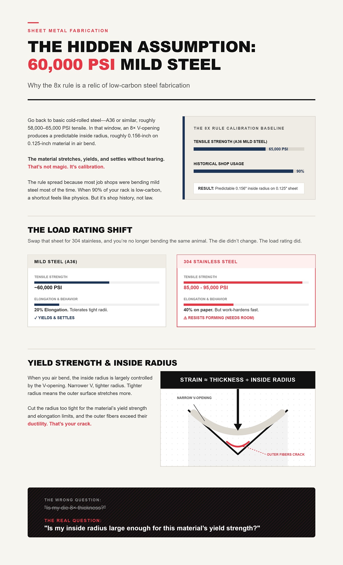
Go back to basic cold‑rolled steel—A36 or similar, roughly 58,000–65,000 PSI tensile. In that window, an 8× V-opening produces a predictable inside radius, roughly 0.156-inch on 0.125-inch material in air bend. The material stretches, yields, and settles without tearing.
That’s not magic. It’s calibration.
The rule spread because most job shops were bending mild steel most of the time. When 90% of your rack is low‑carbon, a shortcut feels like physics. But it’s shop history, not universal law.
Swap that sheet for 304 stainless at 85,000–95,000 PSI tensile, and you’re no longer bending the same animal. The die didn’t change. The load rating did.
And load rating is everything.
When you air bend, the inside radius is largely controlled by the V-opening. Narrower V, tighter radius. Tighter radius means the outer surface stretches more.
Strain on the outside fiber is roughly proportional to thickness divided by inside radius. Cut the radius too tight for the material’s yield strength and elongation limits, and the outer fibers exceed their ductility. That’s your crack.
Mild steel might tolerate 20% elongation. 304 stainless might advertise 40% elongation on paper, but it work-hardens fast and resists forming under tighter radii unless you give it room. High-strength steels? Even less forgiving.
So the real question isn’t “Is my die 8× thickness?”
It’s “Is my inside radius large enough for this material’s yield strength?”
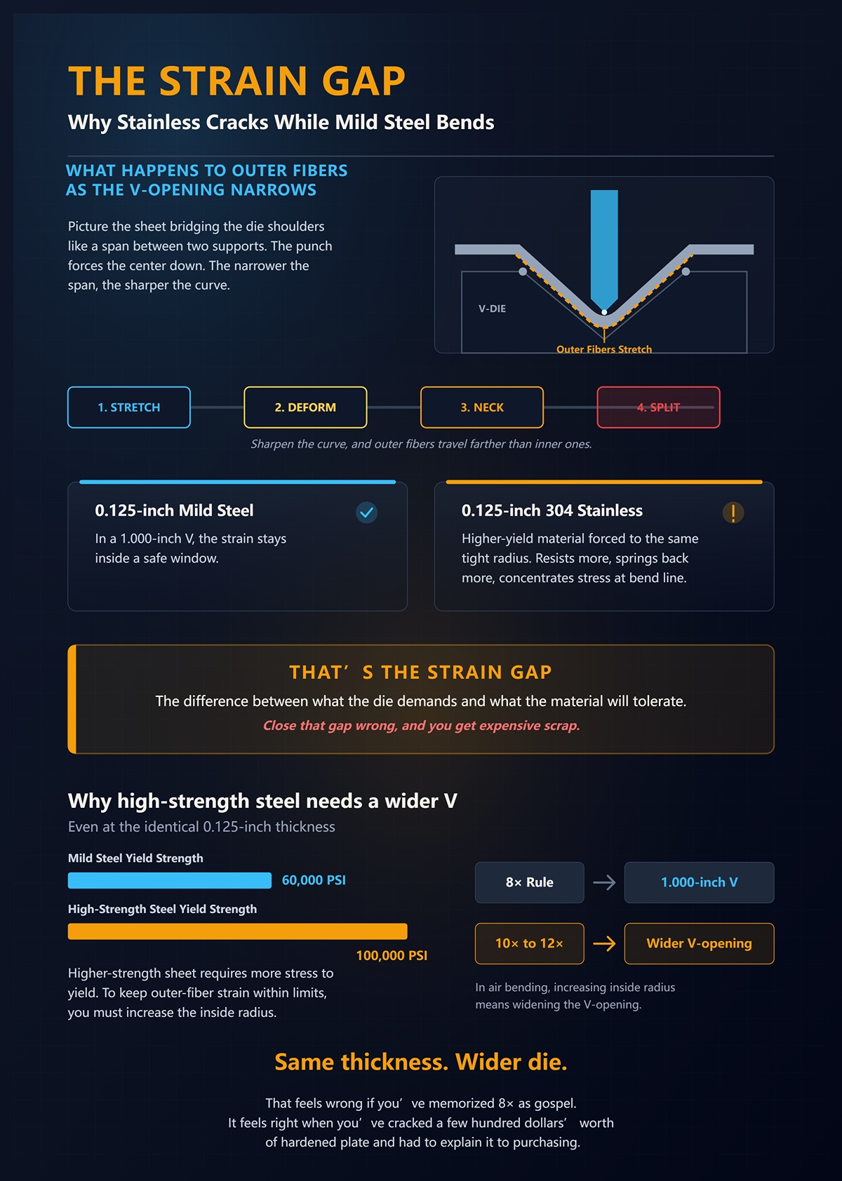
Picture the sheet bridging the die shoulders like a span between two supports. The punch forces the center down. The narrower the span, the sharper the curve.
Sharpen that curve and the outer fibers travel farther than the inner ones. They stretch. Past yield, they plastically deform. Push farther and they neck. Push farther and they split.
On 0.125-inch mild steel in a 1.000-inch V, the strain stays inside a safe window. Put 0.125-inch 304 in that same 1.000-inch V and you’re asking a higher-yield material to stretch to the same tight radius. It resists more, springs back more, and concentrates stress harder at the bend line.
That’s the strain gap—the difference between what the die demands and what the material will tolerate.
Close that gap wrong, and you get expensive scrap.
Take 0.125-inch mild steel at 60,000 PSI and 0.125-inch high-strength steel at 100,000 PSI. Thickness is identical. The 8× rule gives both a 1.000-inch V.
But the higher-strength sheet requires more stress to yield. To keep outer-fiber strain within limits, you increase the inside radius. In air bending, increasing inside radius means widening the V-opening—maybe 10× or even 12× thickness depending on grade.
Same thickness. Wider die.
That feels wrong if you’ve memorized 8× as gospel. It feels right when you’ve cracked a few hundred dollars’ worth of hardened plate and had to explain it to purchasing.
And widening the die changes more than radius.
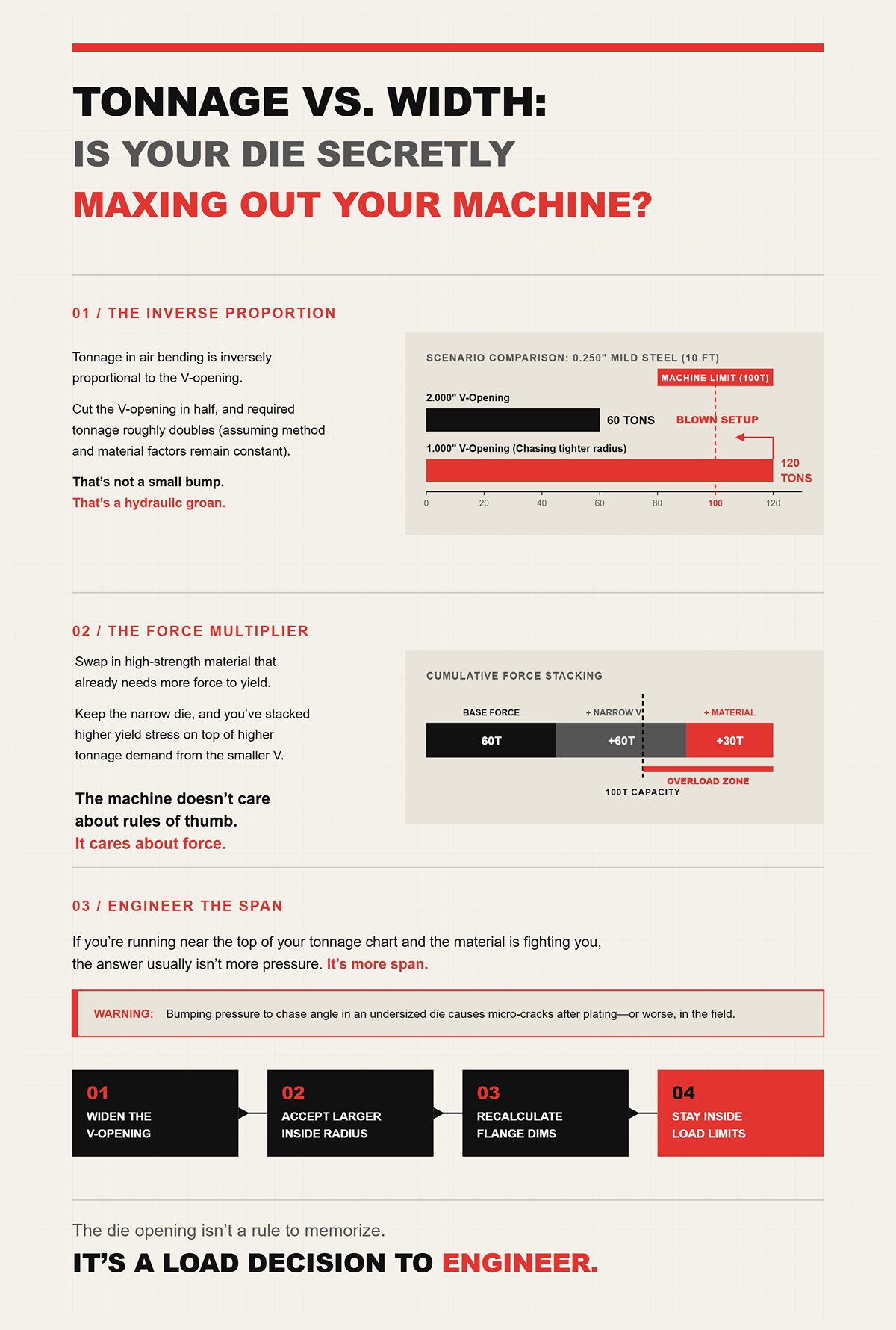
Here’s the part operators miss: tonnage in air bending is inversely proportional to the V-opening.
Cut the V-opening in half, and required tonnage roughly doubles (method factor and material factor constant). That’s not a small bump. That’s a hydraulic groan.
Say you’re bending 0.250-inch mild steel in a 2.000-inch V and you’re at 60 tons over 10 feet. Drop to a 1.000-inch V chasing a tighter radius and you’re flirting with 120 tons (check your chart before you try it). On a 100-ton machine, that’s not theory. That’s a blown setup.
Now swap in high-strength material that already needs more force to yield. Keep the narrow die, and you’ve stacked higher yield stress on top of higher tonnage demand from the smaller V.
The machine doesn’t care about rules of thumb. It cares about force.
I’ve seen operators bump pressure to chase angle on stainless in an undersized die. The angle comes in. The part looks fine. Then micro-cracks show up after plating—or worse, in the field.
If you’re running near the top of your tonnage chart and the material is fighting you, the answer usually isn’t more pressure.
It’s more span.
Widen the V-opening. Accept a larger natural inside radius. Recalculate your flange dimensions. Stay inside the material’s strain limits and your machine’s load limits.
By the end of this, you should feel uneasy reaching for 8× thickness without checking yield strength first.
Good.
Because the die opening isn’t a rule to memorize.
It’s a load decision to engineer.
I watched a 0.125-inch 304 stainless blank get bent in three different dies—0.750-inch V, 1.000-inch V, and 1.500-inch V—same punch, same press brake, same operator. The inside radius changed so much the part wouldn’t fit the same gauge block twice. Nothing else moved. Just the V-opening.
So if 8× thickness isn’t reliable, how do you actually choose the die?
You start by understanding what the die is really doing. In air bending, the V-opening is not a “holder.” It’s the span of a bridge. The sheet rides on the die shoulders, and the punch forces the middle down. That span width dictates how tight the material has to curve to reach 90 degrees. Change the span and you change the curvature. Change the curvature and you change outer-fiber strain, tonnage, and springback. That’s not opinion. That’s mechanics.
And once you see that, you stop asking “What’s the rule?” and start asking “What radius does this span create?”
Take 0.125-inch mild steel in a 1.000-inch V-opening. In air bend, you don’t get a 0.031-inch inside radius because your punch tip is sharp. You get roughly 0.125-inch inside radius. The material “floats” between the die shoulders and settles into its own curve.
That curve isn’t random.
The material forms a natural radius based on how far apart those shoulders are. Wider V, larger natural radius. Narrower V, tighter natural radius. You’re not selecting a die to “fit” thickness. You’re selecting a die to produce a specific inside radius whether you realize it or not.
Which means if your print calls for a 0.250-inch inside radius in 0.125-inch material, you don’t start with thickness. You start by back-solving the V-opening that will float that radius.
So what’s the relationship?
For mild steel up to about 0.500-inch thick, the inside radius in air bending is roughly 15% to 20% of the V-opening. Many charts simplify that to R ≈ V ÷ 8 for 60,000 PSI tensile material. That’s where the old 8× thickness shortcut came from. On 0.125-inch mild steel, 1.000-inch V divided by 8 gives you about 0.125-inch inside radius.
But notice what’s really happening. The radius is a function of V-opening first. Thickness is riding in the background.
Now swap to 304 stainless at 85,000–95,000 PSI tensile. Same 1.000-inch V. You will often see a slightly larger floated radius than mild steel because the higher yield strength resists forming tighter curvature. The percentage creeps. Maybe it behaves closer to V ÷ 7.5 or V ÷ 7 depending on temper. That’s not a failure of the math. That’s the material pushing back.
The key is this: when you change the V-opening, you are directly setting the inside radius window. If your material requires a minimum inside radius of 1× thickness to avoid cracking, you choose a V that produces at least that radius. Not 8× thickness because a chart said so. A V that floats the radius your material can survive.
And that flips the setup sheet on its head.
I’ve had operators insist a 0.062-inch punch tip will “force” a tight radius into 0.250-inch plate sitting in a 2.000-inch V. It won’t. Not in air bending.
The punch contacts the material at the apex, but the sheet is supported at the die shoulders. Until you bottom or coin, the punch tip radius is almost irrelevant to the final inside radius. The material is suspended. It forms to the span, not the nose.
That’s why you can swap from a sharp punch to a 0.125-inch nose and see almost no change in inside radius if the V-opening stays the same. I’ve done it on 0.187-inch A36 in a 1.500-inch V. Angle changed slightly due to penetration depth. Radius didn’t care.
So when someone says, “I need a tighter punch,” what they usually mean is, “I chose the wrong V-opening.”
And if the V-opening sets the radius, what else is it quietly changing?
Bend 0.125-inch 304 stainless to 90 degrees in a 1.000-inch V. You might have to overbend to 83 degrees to land at 90 after springback. Put that same sheet in a 1.500-inch V and now you’re maybe overbending to 80 degrees. Same thickness. Same material. Different die.
Why?
Because springback is elastic recovery. The larger the inside radius, the lower the plastic strain and the higher the percentage of elastic energy stored in the bend zone. Wider V-opening → larger floated radius → less plastic deformation relative to elastic → more springback.
That’s the trade.
On high-strength steels—say 0.125-inch material at 100,000 PSI tensile—the effect gets louder. The material already has a high yield point and a strong elastic range. Put it in a wide V, maybe 1.500-inch or 1.750-inch to protect the inside radius, and you’ve reduced plastic strain even more.
Result? You might see 4–6 degrees of springback on a 90-degree bend (watch your tonnage chart). Operators panic and start adding pressure. Pressure doesn’t change the span. It just drives the punch deeper, flirting with bottoming.
The real lever was the V-opening all along.
Wider die protects against cracking by increasing inside radius. But it can punish you with more angular variation if your machine, tooling alignment, or material lot isn’t consistent. That’s not a reason to go narrow and crack flanges. It’s a reason to understand the balance you’re choosing.
So how do you balance it?
Start with the material’s minimum safe inside radius based on yield strength and elongation. If 0.125-inch high-strength steel needs at least 0.187-inch inside radius to stay out of the danger zone, pick a V that floats that—maybe 1.250-inch or 1.500-inch depending on your shop’s empirical ratio.
Then check two constraints.
First: tonnage. Narrower V means higher force. Tonnage in air bending is roughly inversely proportional to V-opening. Halve the V and you nearly double the required force. Stack that on 100,000 PSI material and you’re into machine limits fast.
Second: geometry. Minimum flange length is typically around 0.67× to 0.77× the V-opening for a 90-degree bend. Choose a 1.500-inch V and you may need roughly 1.000-inch of straight leg just to clear the die shoulders. If your print only gives you 0.750-inch, that die physically won’t work.
Now you’re solving a constraint problem:
That’s die selection. Not 8× thickness.
And once you understand that the V-opening controls the natural radius and the springback behavior in air bending, you’re ready to ask the next uncomfortable question:
What changes when you stop air bending and start bottoming or coining?
What mechanically changes when you stop air bending and start bottoming or coining?
You stop letting the material choose its radius.
In air bending, the sheet is suspended between die shoulders like a bridge span, and the punch just pushes it into a curve until plastic deformation overcomes elastic recovery. The V-opening sets the span width. The material yields where it wants, within that geometry. Springback is predictable because you never fully trap the sheet.
Bottoming and coining are different animals.
They turn the die from a support into a mold.
And when the die becomes a mold, the wrong V-opening doesn’t just give you the wrong radius — it multiplies force, stress, and expensive scrap.
In air bending, the punch never drives the sheet into full contact with the die walls and bottom. Three points of contact. That’s it. Two shoulders and the punch tip.
The sheet is free to “float” its inside radius based on span width and material yield strength. That’s why a 1.000-inch V might float around 0.125-inch inside radius in mild steel but behave differently in 0.125-inch 304 stainless. The die is defining limits, not enforcing shape.
You are guiding the material, not trapping it.
That freedom is why air bending tolerates a range of V-openings for the same thickness. You can run 0.125-inch A36 in a 1.000-inch V or a 1.250-inch V and still land the job if you manage springback and flange limits. Tonnage changes (watch your chart), radius changes, overbend changes — but the process is forgiving because the sheet isn’t being crushed into geometry.
The die is a support.
And supports don’t dictate curvature — they allow it within boundaries.
Because you never fully seat the material into the die, small changes in V-opening shift the floated radius and springback in a smooth, proportional way. Halve the V-opening and you nearly double tonnage. Widen it and you increase springback. But the material still finds its own equilibrium between elastic and plastic strain.
It’s adjustable.
You can compensate with penetration depth, angle correction, or material testing. Even if you undersize the V slightly, the sheet isn’t being ironed flat against hardened steel. You might see tighter radius and higher tonnage, but you’re not automatically forcing it past its strain limit.
That’s why air bending feels forgiving when your material lot shifts 5,000 PSI in yield strength.
The system has elasticity built into it.
But here’s the part most operators don’t say out loud.
Air bending trades some angular precision for that flexibility.
Because you rely on springback compensation, your final angle depends on consistent material properties, consistent penetration depth, and a press that repeats within a few thousandths. On a tight-tolerance aerospace bracket in 0.090-inch 7075-T6, that variability shows up fast. You can hold it. But you’re managing it.
That’s where bottoming and coining start looking attractive.
They promise to “lock” the angle.
The question is what that lock costs.
Bottoming changes one thing that matters more than all the rest.
You drive the material into the die cavity until it contacts the die angle and then you push past initial contact — typically compressing the bend zone an additional 10–15% to reduce springback. Now the sheet isn’t floating between shoulders. It is wedged into geometry.
You’re no longer allowing the radius to form naturally.
You’re forcing it.
And when you force metal, the tonnage gauge tells the truth.
In air bending, you might see 1–2 tons per inch on 0.125-inch mild steel in a 1.000-inch V. Bottom that same setup and you can easily double or triple that load depending on die angle and penetration. The press brake doesn’t care about your rule-of-thumb chart anymore. It cares about contact area.
Now imagine you followed the 8× thickness rule and chose a V that’s too narrow for the material’s minimum inside radius.
In air bending, that might have shown up as a tighter radius and higher tonnage — a warning. In bottoming, you’re crushing the bend zone into a die angle that may be sharper than the material can tolerate. The extra 10–15% penetration to “lock” the angle increases compressive stress at the inside surface and tensile strain just outside the neutral axis.
That’s where flanges split.
And tooling manufacturers discourage bottoming for a reason. When you fully seat material into hardened dies under elevated tonnage, any mismatch in V-opening, die angle, or material ductility transfers straight into tool wear, galling, or chipped shoulders. It feels right when you’ve cracked a few hundred dollars’ worth of hardened plate and had to explain it to purchasing.
Bottoming reduces springback.
It also reduces your margin for being wrong about the V-opening.
Coining isn’t bottoming turned up a little.
It’s a different regime.
You drive the punch tip into the material with enough force — often 50 tons per inch or more, compared to 1–2 in air bending — to plastically deform the entire bend zone through thickness. You’re not just bending. You’re ironing. The punch nose radius becomes the inside radius because you are displacing material under extreme compressive stress.
Springback nearly disappears because you’ve exceeded yield everywhere in that zone.
But the 8× rule?
Meaningless here.
In coining, the V-opening must be matched to punch geometry and material strength so the material can flow without fracturing or destroying tooling. Too narrow and tonnage spikes beyond machine capacity. Too wide and you lose support, distort the angle, or mark the part. Geometry options shrink because the tooling has to survive the load.
This is why coining is rare in modern shops. Not because it doesn’t work — it absolutely does — but because it demands specialized tooling, rigid machines, and disciplined setup. Get the V-opening wrong here and you won’t just see angle drift.
You’ll hear it.
A sharp report from the press, a spike on the tonnage meter, and sometimes a cracked punch tip that just turned your setup into expensive scrap.
Air bending lets the material find its radius. Bottoming and coining impose one.
Once you understand that difference, die selection stops being a thickness shortcut and becomes a load-management decision — like sizing a bridge span for the weight it must carry.
So if the bending method changes how the radius is created and how force flows through the tooling, how do you turn that into a repeatable way to choose the right V every time?
I watched a 0.125-inch 304 stainless bracket crack clean through the outside radius in a 1.000-inch V because the setup sheet said “8× thickness.” The operator did nothing wrong. The rule was wrong for that load.
If bending method changes how force flows, then V selection has to start with the material’s load rating — its yield strength — not its thickness. Here’s the workflow I use on the floor, the same one that’s kept me from making expensive scrap on 7075-T6 and high-strength plate.
Pull the cert.
Not the generic “stainless” line from the traveler. The actual yield strength from the mill test report. A36 might show 36,000 PSI yield. Cold-rolled 1018 can land around 50,000–60,000 PSI. 304 stainless is often 30,000–45,000 PSI yield but strain-hardens fast. 7075-T6 aluminum sits around 73,000 PSI yield. HSLA grades can push well past that.
Yield strength tells you how much stress the outer fibers can take before they plastically stretch. The tighter the radius, the higher the outer-fiber strain. That’s the crack mechanism.
Those “6× for aluminum, 10× for stainless” multipliers floating around shops? They’re rough translations of yield strength into survivable strain. But aluminum isn’t one thing. 5052-H32 bends beautifully. 7075-T6 snaps if you look at it wrong. Same thickness. Completely different strain tolerance.
But it’s shop history, not universal law.
So I treat the multiplier as a starting guess tied to yield range, not material name. Under 40,000 PSI yield? You can usually live with tighter ratios. Around 60,000 PSI? You’re in classic mild-steel territory. Over 70,000 PSI? You start widening dies fast to protect the outer fibers.
If you don’t start with yield, you’re guessing about strain. And guessing about strain is how flanges split.
Here’s how that looks in practice.
Suppose you’ve got 0.125-inch 5052-H32 aluminum. Yield around 28,000–33,000 PSI. That material tolerates tighter radii, so a 6× thickness V (0.750-inch) in air bending often behaves well.
Now swap to 0.125-inch 304 stainless, yield maybe 35,000–45,000 PSI, but with aggressive work hardening. If you stick with 0.750-inch because “it worked on aluminum,” your inside radius shrinks, outer strain spikes, and you’ll see micro-cracking on polished parts. Bump toward 1.250-inch or 1.500-inch V and the material relaxes.
Take 0.125-inch HSLA at 80,000 PSI yield. If you try to force it into a 1.000-inch V because the rack is organized in doubles, you’re concentrating strain into a radius the material simply cannot survive. That’s not a thickness problem. That’s a yield problem.
So once you know yield, the next question writes itself.
What inside radius will that material survive without tearing?
I’ve seen 0.187-inch A36 bent to a 0.187-inch inside radius all day long. Try that stunt with 0.187-inch 4140 prehard and you’ll be sweeping up shards.
The outer surface of a bend stretches. The tighter the inside radius relative to thickness, the higher the tensile strain outside. When that strain exceeds the material’s elongation capacity at yield, you get cracking. That’s the physics.
For air bending, a safe rule for many steels around 60,000 PSI tensile is an inside radius roughly equal to material thickness. That’s why the old “8× thickness” sometimes works on mild steel — because air bending in an 8× V tends to produce an inside radius near 1× thickness.
But move away from that tensile range and the relationship shifts.
Higher-strength materials need larger inside radii relative to thickness to keep outer-fiber strain below fracture limits. That’s why 7075-T6 often wants 2× thickness or more for a reliable 90-degree bend. Ignore that and you’ll hear the crack before you see it.
So you choose a target IR based on yield and ductility — not because a chart said 8× thickness, but because the material’s strain capacity demands it.
Once you have that target radius, the die becomes geometry.
Let’s run a real scenario.
You’ve got 0.125-inch 304 stainless, cosmetic face out. Based on yield and experience, you decide you want at least a 0.125-inch inside radius to stay out of the crack zone. Tighter than that and you’re gambling with the finish.
That 0.125-inch IR is the constraint. It protects the material.
Now the question becomes mechanical: what V-opening produces that radius in air bending?
In air bending, the inside radius is controlled primarily by the V-opening, not the punch tip. A common approximation is that the inside radius equals about 16% of the V-opening.
Flip that around.
If IR ≈ 0.16 × V, then V ≈ IR ÷ 0.16.
If you want a 0.125-inch inside radius:V ≈ 0.125 ÷ 0.16 ≈ 0.781 inch.
You’re not going to find a 0.781-inch die on the rack. You’ll choose the closest standard — probably 0.750-inch or 1.000-inch.
Now compare outcomes.
0.750 × 0.16 ≈ 0.120-inch IR. 1.000 × 0.16 ≈ 0.160-inch IR.
If cracking is your concern, the 1.000-inch V gives you margin. If flange length is tight and you need a smaller die for support, you might accept the 0.750-inch and monitor the surface carefully.
See what just happened?
You didn’t start with thickness. You started with allowable strain, translated that into a target radius, and then backed into a V-opening that manages the load.
That’s load management on a bridge. The roadway (material) has a load rating (yield). You size the span (V-opening) so the stress never exceeds it.
Given that CN-HAWE’s product portfolio is 100% CNC-based and covers high-end scenarios in laser cutting, bending, grooving, shearing, for teams evaluating practical options here, Press Brake is a relevant next step.
But geometry and force still get a vote.
If you’re validating a specific print, material grade, or machine limit, this is the point where real-world constraints—available tonnage, tooling inventory, and forming method—have to be checked together. CN-HAWE supports fully CNC-based bending and sheet metal solutions and invests heavily in R&D across press brakes and intelligent equipment, making it a practical partner for reviewing tonnage calculations, V-die selection, and process feasibility against your actual production conditions. For a technical discussion or quotation, you can contact CN-HAWE here.
When you hear “8:1 ratio” used correctly, it’s not 8× thickness. It’s roughly V ≈ 8 × IR, which lines up with that 16% relationship (since 1 ÷ 0.16 ≈ 6.25 and real-world variation pushes it closer to 8 depending on material and penetration).
That ratio only works if your bending method is air bending and your material behaves near that strain curve. Bottoming or coining breaks this relationship because the die angle and punch radius take control.
So the 8:1 idea isn’t evil.
It’s just been attached to the wrong variable.
And once you pick a V from radius, you still haven’t answered the question that keeps presses alive:
Can your tooling and machine survive the load?
I’ve seen a 0.250-inch plate job spec’d into a narrow die that calculated at over 150 tons total on a 10-foot brake rated for 135. The math was right on radius. The machine didn’t care.
Air bending tonnage rises as V-opening narrows. Double the V and you nearly halve the tonnage requirement. That’s because a narrower span concentrates force over a shorter lever arm. The die becomes a shorter bridge span carrying the same truck.
So once you’ve selected a V from your target IR, calculate tons per foot for that thickness and V-opening. Compare it to:
(And if you’re bottoming, multiply your air-bend tonnage substantially — often 2× or more — because contact area and penetration spike load.)
This is where the “we only stock 0.500, 1.000, and 2.000-inch dies” argument falls apart. Yes, you can cover a lot of jobs that way. You can also quietly over-stress tooling or ride the edge of cracking on high-strength parts and call it “normal variation.”
It feels right when you’ve cracked a few hundred dollars’ worth of hardened plate and had to explain it to purchasing.
So the workflow is simple, but it isn’t simplistic:
Do that, and the 8× thickness shortcut stops running your shop.
Now there’s one more constraint that can still wreck this perfectly calculated setup — and it has nothing to do with strength.
You can have the yield right, the inside radius right, the V-opening calculated off 0.16 × V, and the tonnage safely under your machine’s rating — and still scrap the part.
I watched a 0.125-inch 304 stainless bracket run in a perfectly reasonable 1.000-inch V-die. Radius came out at 0.160. Tonnage was comfortable. Surface didn’t crack. But the print called for a 0.375-inch flange. Every piece came off short on leg length and long on angle, like the brake had a mind of its own.
It didn’t.
The flange was too short for the die geometry.
When the leg can’t physically sit flat on the die shoulder during the bend, the sheet stops behaving like a supported span and starts behaving like a diving board. Your strain math doesn’t change. Your support condition does. And geometry will win that fight every time.
So if strength isn’t the failure point, what is?
Put a caliper on a 1.000-inch V-die. From centerline to each shoulder is 0.500 inch. When you air bend, the material contacts near those shoulders as the punch drives down. That contact patch is your support.
Now imagine trying to bend a 0.375-inch flange in that same die. Half the V (0.500 inch) is already wider than your entire leg. There is no stable shoulder support. The material drops into the V before the bend fully forms.
You’ll chase angle all day.
Because what’s happening isn’t springback. It’s shifting geometry. The blank is sliding deeper into the die as you apply load. Your bend line is effectively moving. That’s why your angle measurement floats even when your tonnage is dead consistent.
Angle errors look like material problems.
They’re often leg-length problems.
And this is where the 8× thickness crowd gets trapped. You selected the V correctly from yield and target IR. Good. But nobody asked whether the flange can physically exist in that V.
So how do you know before you hit cycle start?
Here’s the practical check.
For air bending, minimum flange is roughly 0.7 × V-opening. Some shops use 0.6 × V. Some play it safe at 0.8 × V. But if you’re below 0.6 × V, you are gambling.
Take that 1.000-inch V.
0.7 × 1.000 = 0.700-inch minimum flange for stable support.
Now compare that to the 0.375-inch flange on the print. You’re at barely 0.375 × V. That leg has no chance of sitting squarely on the shoulder during forming.
So what did the operator do? He swapped to a 0.625-inch V-die. That violates the old 8× thickness rule for 0.125-inch material (0.625 ÷ 0.125 = 5×). But geometrically?
0.7 × 0.625 = 0.437-inch minimum flange.
Now your 0.375-inch leg is still tight — but at least it’s in the realm of physical support.
Here’s the catch.
Narrowing that die didn’t just fix geometry. It spiked tonnage. On 0.250-inch A36, I’ve measured roughly 300 tons per 10 feet in a 1.500-inch V versus about 139 tons in a 3.000-inch V. Cut the span in half and the load more than doubles. Same physics applies at lighter gauges.
You solve flange support and quietly load the brake harder.
That’s how “quick fixes” become expensive scrap or worse, expensive tooling.
And if the flange is even shorter?
When the flange is too short, it doesn’t just lose support. It can tip into the V as the punch penetrates.
You’ll see a shiny drag mark along one shoulder. That’s not cosmetic. That’s the blank rotating as it falls into the die. The bend line shifts inward, effectively shortening your leg beyond the developed length you calculated.
Now your flat pattern is wrong — even though your bend deduction math was right.
This is where newer force models matter. Real-world testing on SPCC and 1100-O aluminum has shown actual bending loads often exceed chart values under non-ideal contact conditions. Slippage is one of those conditions. You get point loading instead of clean shoulder contact. Local pressure climbs. Marking increases. Force prediction goes out the window.
So minimum flange isn’t a suggestion.
It’s a stability requirement.
But let’s say your flange clears the 0.7 × V rule. You’re supported. Angle is consistent. There’s another quiet geometry problem that creeps in — especially when you try to be “efficient” with your tooling rack.
I like multi-V blocks. They save space. You can flip from 0.500 to 0.750 to 1.000 in one tool.
But measure them.
The shoulders on a multi-V are narrower. The land between adjacent openings is thinner. Under load — especially north of 20 tons per foot — they deflect more than a dedicated single-V of the same opening.
Deflection changes your effective V-width under pressure.
And that changes your radius.
Run 0.187-inch A36 in the smallest opening of a multi-V block rated for light gauge. You’ll get angle variation across the length that you won’t see in a solid single 0.750-inch die.
Why?
Because at the extreme of its rating, the die body flexes microscopically. That flex widens the opening under load. Wider V means larger inside radius. Larger radius means more springback. So your programmed depth no longer equals your target angle.
It’s subtle. A degree here. A degree and a half there.
On a ±0.5° tolerance job, that’s scrap.
This doesn’t mean multi-V blocks are junk. But it’s shop history, not universal law — they’re fine in the middle of their working range. Push them to the edge and geometry drifts.
So when do you stop being flexible?
If the print calls for ±0.010-inch flange length and ±0.5° angle on 0.125-inch 304 stainless, and you’re running 15–20 tons per foot, buy the dedicated die.
A single 0.875-inch or 1.000-inch V with full mass under it will hold geometry better under load. Less deflection. More consistent radius. More predictable springback.
Yes, it costs more up front.
So does remaking a 200-piece run because the last 30 parts drifted out of tolerance as the die warmed and flexed.
And when flange length and die mass still aren’t enough?
Some parts don’t just fight you on strength or flange length. They fight you on surface, springback, or both.
That’s when standard V-dies stop being the right tool.
Cosmetic 0.090-inch 5052 with a brushed face will show every shoulder mark. You can widen the V to reduce pressure, but that increases radius and springback. Now your angle floats.
A roller die changes the contact condition. Instead of sliding across a fixed shoulder, the material rolls. Lower friction. Less marking. More consistent force curve.
Urethane inserts spread the load over a broader surface, reducing peak pressure without forcing you into an oversized V. Geometry stays closer to your calculated radius.
You’re managing contact mechanics now, not just span width.
Different lever. Same goal.
Take 0.187-inch 80,000 PSI material that springs back 6–8 degrees in a standard 90° V. You can overbend with depth, but penetration climbs and tonnage follows.
An acute 30° or 60° V-die changes the geometry of bottoming without fully coining. The die walls engage earlier. You control springback with angle constraint instead of brute force.
Yes, tonnage increases (watch your tons per foot), but you’re trading depth for angular control. On high-yield parts, that can mean the difference between a stable 90° and chasing it all shift.
At this point, the pattern should be clear.
Yield strength told you how tight you could bend without cracking. Tonnage told you whether the machine survives. Flange length tells you whether the part can physically sit in the die. Tool geometry tells you whether that setup will hold tolerance under load.
Ignore any one of them, and you’re back to making expensive scrap — even with perfect strain math.
So the real workflow isn’t “8× thickness.”
It’s strain capacity, load capacity, and physical support — in that order.
You want the workflow.
Not a ratio. Not “8×.” A sequence that keeps 0.125-inch 304 stainless from turning into expensive scrap while still holding ±0.5° and ±0.010-inch on the flange.
Here’s the shift: stop picking a V-opening like it’s a gap to fill. Start picking it like you’re setting the load rating on a bridge. The sheet is the roadway. Yield strength is the load. The V-opening is the span. Undersize the span for the load and something cracks. Oversize it and the roadway sags — your radius grows, springback climbs, angles wander.
So the decision runs in one direction only:
That’s the order. Break it and you’re back to gambling.
Why start there?
Because the metal doesn’t care about your rule of thumb. It reacts to strain.
“Material first” does not mean “thickness first.”
It means yield strength first.
If you hand me 0.187-inch A36 and 0.187-inch 304 stainless, and you tell me to use the same 1.500-inch V because “that’s what we always run,” I already know one of those parts is at risk. Same thickness. Different strain capacity. Different springback. Different tonnage per foot.
But it’s shop history, not universal law — 8× works fine on 36,000–60,000 PSI mild steel when you’re not chasing tight tolerances. The trap is assuming that success transfers to 70,000–90,000 PSI stainless or abrasion-resistant plate.
So the checklist starts like this:
Now you have constraints.
Without that, you’re browsing tooling like it’s a catalog problem instead of a strain problem.
Let’s make it concrete.
Say the print calls for 0.125-inch 304 stainless, 90°, inside radius 0.125-inch max, ±0.5°, flange length 0.750-inch.
Step one: radius drives V in air bending. For most steels, inside radius floats at roughly 0.16 × V. So if I want about 0.125-inch inside radius:
0.125 ÷ 0.16 ≈ 0.781-inch V.
Nearest real tool is 0.750 or 0.875.
Now check strain reality. 304 will tolerate an inside radius around 1× thickness in many tempers without cracking. 0.125 on 0.125 is 1T. We’re in the survivable zone.
Now tonnage. A tighter V increases tons per foot. If that 0.750-inch V pushes me north of, say, 18–20 tons per foot on this material (check your chart), I’d better confirm the die and brake are rated for it. I watched a 0.125-inch stainless job mushroom a light multi-V because someone ignored the per-foot rating and just looked at total tonnage.
Then flange length. 0.7 × 0.750 = 0.525-inch minimum. Print calls for 0.750-inch. We’re supported.
Now — and only now — do I open the cabinet.
Notice what didn’t happen.
We never said “8× thickness.” We said, “What strain can this material survive, and what V produces that strain?”
That’s control.
Most operators blame depth or springback compensation first.
Sometimes they’re wrong.
Cracking at the bend line on stainless?
Check the actual inside radius you’re creating. If you grabbed a 1.000-inch V on 0.125-inch 304 because it “felt safer,” your radius floats around 0.160-inch. That reduces cracking risk, yes — but it increases springback. So you drive deeper to chase 90°. Deeper means more penetration, more contact pressure at the shoulders, and sometimes localized overstrain.
The crack wasn’t from being too tight.
It was from losing control of the strain path.
Heavy shoulder marks on cosmetic 0.090-inch 5052?
Before you blame punch finish, ask if the V is too narrow for the yield strength. Narrow V equals higher contact pressure. Pressure leaves tracks. Widening the V reduces marking but grows the radius. If angle tolerance is tight, that trade shows up as inconsistency across the batch.
Inconsistent angles left to right on a long part?
If you’re near the top end of a multi-V die’s tonnage rating, the body flexes. The opening effectively widens under load in the center. Wider V in the center means larger radius, more springback, more open angle.
That’s not a depth issue.
That’s span deflection.
When you see the symptom, ask one question: is the V-opening forcing the material into a strain condition or load condition it can’t hold consistently?
If yes, the fix isn’t more stroke.
It’s a different span.
You’re not folding sheet.
You’re directing material flow between two shoulders while staying inside its strain limit and your machine’s load limit.
That’s a control problem, not a gap problem.
Catalog thinking says: 0.125-inch material → 1.000-inch V → done.
Strain thinking says: What radius do I need? What V produces it? What tons per foot does that require? Can my die body hold that without deflecting? Does the flange physically sit stable at 0.7 × V or more?
That sequence turns bending from habit into engineering.
And once you run jobs that way for a year, something changes. You stop asking, “What V do we usually use?” and start asking, “What strain am I creating?”
That’s the one thing to carry forward.
The metal doesn’t know your rule. It only knows the stress you put into it.
Control the strain, and the rest — tonnage, angle, tolerance, tool life — lines up behind it.


