

Three months after install, the enclosure door starts sagging. The screws are still there. Heads tight. But the latch doesn’t line up anymore, and when you pull one screw out, the hole isn’t threaded steel — it’s an oval crater.
I’ve scrapped panels for less.
Somewhere along the way, we started treating sheet metal screws like paper clips: if they fit, they work. That thinking is expensive.
I watched a junior designer tap M4 threads into 1.0 mm mild steel for a control panel. “We’ve got three threads,” he said, proud of his calipers. On paper, that sounds like engagement. On the floor, it’s a countdown.
Because those three threads aren’t carrying load the way you think. The screw isn’t hanging from neat little helical shelves. It’s wedging the sheet apart, crushing material in front of the thread flank, and trying to tilt under load. Thin sheet doesn’t fail politely. It distorts first. Quietly.
So when that joint loosens, what actually gave up?
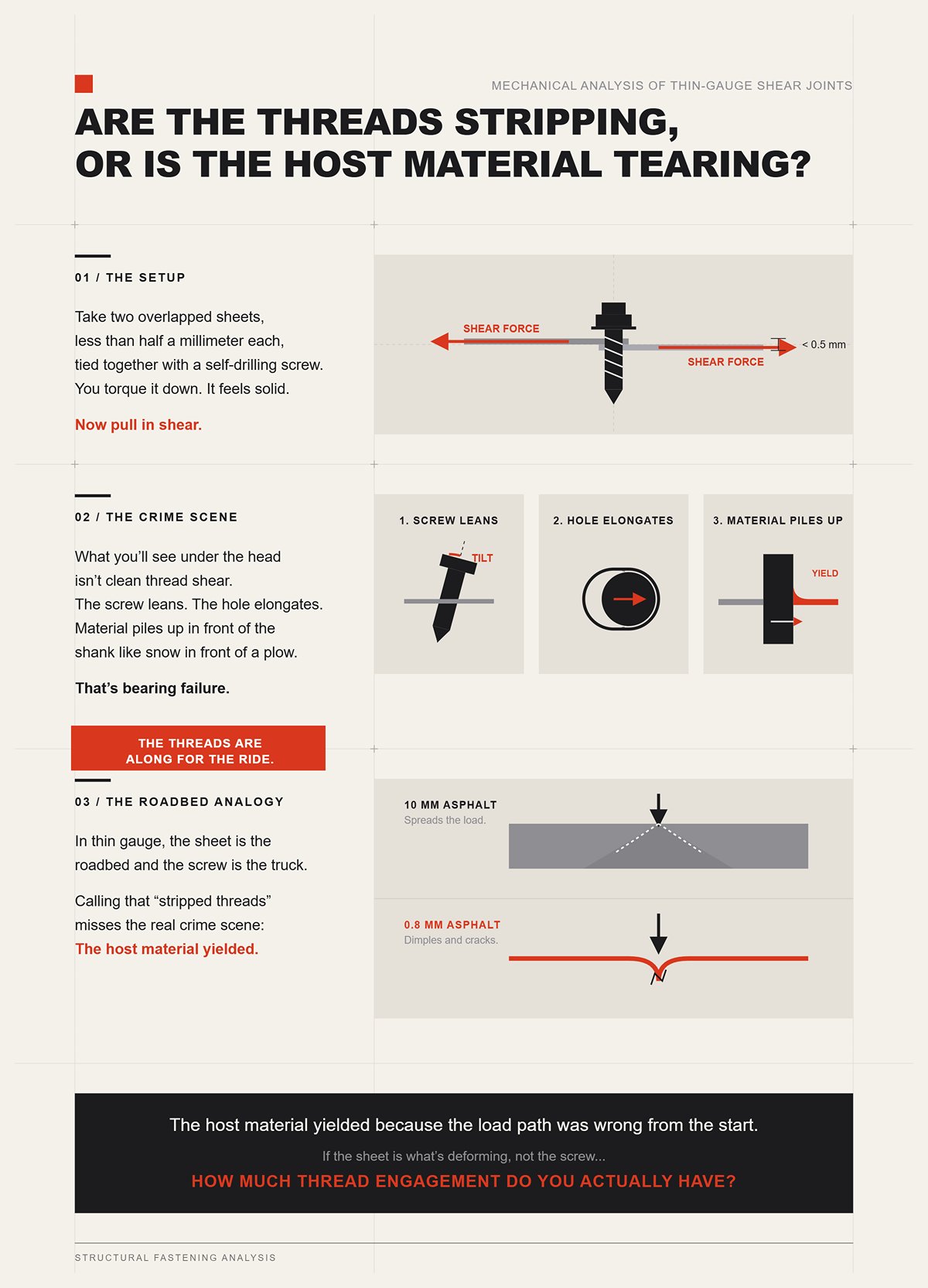
Take two overlapped sheets, less than half a millimeter each, tied together with a self-drilling screw. You torque it down. It feels solid. Now pull in shear.
What you’ll see under the head isn’t clean thread shear. The screw leans. The hole elongates. Material piles up in front of the shank like snow in front of a plow. That’s bearing failure — the screw crushing and displacing the sheet — usually mixed with tilting.
The threads are along for the ride.
In thin gauge, the sheet is the roadbed and the screw is the truck. If the asphalt is 10 mm thick, it spreads the load. If it’s 0.8 mm, it dimples and cracks. Calling that “stripped threads” misses the real crime scene: the host material yielded because the load path was wrong from the start.
If the sheet is what’s deforming, not the screw, how much thread engagement do you actually have?
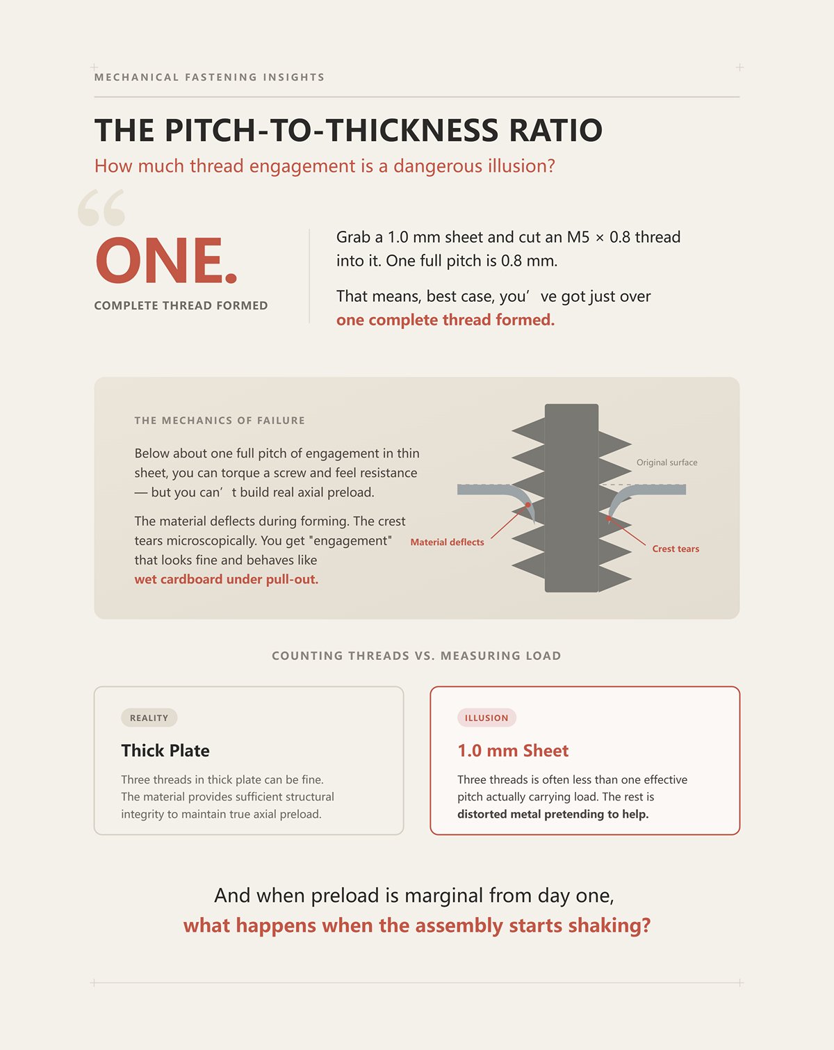
Grab a 1.0 mm sheet and cut an M5 × 0.8 thread into it. One full pitch is 0.8 mm. That means, best case, you’ve got just over one complete thread formed.
One.
Below about one full pitch of engagement in thin sheet, you can torque a screw and feel resistance — but you can’t build real axial preload. The material deflects during forming. The crest tears microscopically. You get “engagement” that looks fine and behaves like wet cardboard under pull-out.
That’s the illusion: counting threads instead of measuring load capacity.
Three threads in thick plate can be fine. Three threads in 1.0 mm sheet is often less than one effective pitch actually carrying load. The rest is distorted metal pretending to help.
And when preload is marginal from day one, what happens when the assembly starts shaking?
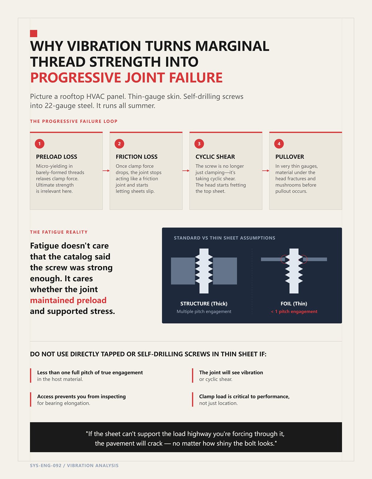
Picture a rooftop HVAC panel. Thin-gauge skin. Self-drilling screws into 22-gauge steel. It runs all summer.
The first thing vibration attacks isn’t ultimate strength. It attacks preload. Any micro-yielding in those barely-formed threads relaxes clamp force. Once clamp force drops, the joint stops acting like a friction joint and starts letting the sheets slip.
Now the screw isn’t just clamping — it’s taking cyclic shear. The head starts fretting the top sheet. In very thin gauges, you often see pullover before pullout: the material under the head fractures and mushrooms because that thin ring of steel is doing all the work.
Fatigue doesn’t care that the catalog said the screw was strong enough. It cares whether the joint maintained preload and whether the sheet could support the bearing stresses cycle after cycle.
Standard fasteners assume the material around them is thick enough to behave like structure, not foil. Thin sheet breaks that assumption. Quietly. Predictably.
Do not use directly tapped or self-drilling screws in thin sheet if:
If the sheet can’t support the load highway you’re forcing through it, the pavement will crack — no matter how shiny the bolt looks.
I had a batch of 1.2 mm control box panels that looked perfect on paper. Spec’d for M6 self-clinching nuts. Press force dialed in. Torque test passed at incoming. Then final assembly hit the line, and half the nuts spun in place.
Not stripped. Not pulled out. Spun.
Upstream, someone had switched to a harder temper sheet to reduce denting during transport. Nobody told engineering. The press still hit the same force. The nuts seated flush. But the sheet didn’t flow the way it was supposed to, so the locking ring never fully formed. We had built 400 spin-out generators.
That’s the difference between screwing into thin sheet and clinching into it. A self-clinching fastener doesn’t rely on fragile threads cut into foil. It reshapes the sheet so the sheet becomes part of the hardware. The load path isn’t hanging on thread flanks anymore; it’s locked behind a cold-formed shoulder. The sheet stops being pavement and becomes the guardrail.
But only if the metal actually moves.
Take a standard flush-head clinch nut and look at the cross-section. There’s a serrated or undercut ring just beneath the head. During installation, a parallel punch forces the nut into a punched hole slightly larger than the shank. The sheet yields locally and flows radially into that undercut.
No cutting. No chips. Just plastic deformation.
That local yielding is cold flow — permanent reshaping at room temperature. The material displaces into the groove, and once it’s there, the only way out is to shear that ring of sheet metal or tear it out in tension. Now your load path isn’t a couple of fragile thread crests. It’s a full 360-degree mechanical interlock.
In pull-out, the resisting area is roughly the circumference of the undercut times the thickness of the displaced sheet. Double the diameter, and you double the shear perimeter. Increase thickness, and you increase the resisting area linearly. That’s math you can design around.
But here’s what most catalogs don’t emphasize: the sheet’s ability to flow is finite. In thin gauges under about 1.0 mm, especially high-strength steels, the localized strain around the hole can approach the forming limit. I’ve seen quarter-buckling around clinch sites where the material piled unevenly, leaving one side thin and work-hardened. Under vibration, that hardened crescent cracked first.
Cold flow creates strength because it redistributes material into a geometry that resists rotation and pull-out. Cold flow also consumes ductility. Push it too far — too large a fastener in too thin a sheet — and you’re necking the very material you’re counting on to hold.
So the real question isn’t “Does clinching add thickness?” It doesn’t. The question is: does your sheet have enough ductility reserve to survive the reshaping and still carry service loads afterward?
Which metal is supposed to give first?
I’ve pressed a clinch nut into 5052-H32 aluminum and watched it seat like butter. Same nut into high-strength low-alloy steel that had been pre-cold-worked? Installation force jumped hard, press deflected, and the nut sat proud by a few thousandths.
The rule is simple and brutal: the sheet must yield; the fastener must not.
Self-clinching hardware is heat-treated to be significantly harder than the host sheet. When the punch drives it in, the sheet flows into the undercut while the fastener maintains its geometry. Reverse that hierarchy — harder sheet, softer hardware — and instead of the sheet filling the groove, the groove smears or the sheet barely moves. You end up with cosmetic seating and no real lock.
There’s data from forming studies that shows pre-cold-working sheet metal can raise required installation force by 20–30% without delivering proportional gains in joint strength. That extra force isn’t buying you holding power; it’s fighting a material that no longer wants to deform. You stress the press, risk panel distortion, and still don’t get deeper interlock.
And even when you do get proper seating, you’ve created a cold-worked zone around the hole. Residual stresses live there. In ferrous sheets, especially if coatings are damaged during pressing, that stressed ring can become a corrosion initiation site. I’ve seen outdoor enclosures where every rust bloom started at a clinch nut perimeter.
Forcing the metal to do the work is powerful. It is not free.
So when does all that reshaping actually beat a rivet or a loose nut?
Picture a 1.5 mm steel bracket that needs an M5 thread for a motor mount. Option one: drill clearance, use a bolt and loose nut. Option two: blind rivet plus threaded insert. Option three: self-clinching nut.
With a loose nut, your clamp load is fine — as long as someone can hold the backside and you never lose preload. But your shear capacity between sheets still depends on friction from clamp force. Lose preload under vibration, and the bolt starts seeing bending. The screws are still there. The joint isn’t the same.
A blind rivet gives you solid shear because the body fills the hole, but you don’t get reusable threads. Add a threaded insert rivet nut, and now you’re depending on thin-wall expansion against the hole. In thin sheet, that expansion often leads to local bulging. What you’ll see under the head isn’t clean thread shear. It’s bearing distortion around a deformed hole.
A properly specified clinch nut changes the math. Your pull-out resistance is tied to the shear area of the interlocked ring. Your torque-out resistance is tied to the diameter and shape of the knurled or serrated undercut embedded in the sheet. And because the threads are in full-thickness hardened steel, you get real preload — not one pitch pretending to be structure.
In repeat assemblies — service panels, electronics chassis, motor covers — that combination matters. You can torque to spec, remove and reinstall, and the load path remains in the hardened fastener, not in sacrificial sheet threads.
But clinching demands two things: enough ductility to form the lock and access for a parallel press during installation. No ductility, no lock. No press access, no installation.
So the method that fixes the load path in open, formable sheet still leaves you stuck when you only have one side and no room for a press.
What do you do when you can’t force the metal to flow because you can’t even reach the back side to support it?
I once had a powder‑coated enclosure come back from the field with every M6 fastener still torqued to spec — and every insert spinning in place. The screws were tight. The panel was junk. We had no backside access for a press, so we chose rivet nuts. Installed with a hand tool. Production moved on. Three months later, a tech leaned on a wrench, and the insert machined its own hole.
That’s the trade you make when you can’t clinch. A blind insert doesn’t create a cold‑flow interlock by reshaping the sheet into a hardened undercut. It collapses on itself, mushrooms behind the panel, and clamps thin material between its head and its upset body. It’s wedging the sheet apart, crushing material in front of the thread flank, and trying to tilt under load. The load path is no longer a formed ring of displaced steel. It’s friction, bearing, and whatever deformation you created during installation.
So the question isn’t “Will it hold?” It’s: under what force does it let go first?
Picture a 1.2 mm mild steel panel with an M5 rivet nut holding a bracket. Someone hangs a 20 lb component off it. Gravity doesn’t care about your catalog ratings. It creates a moment at the insert face. That moment resolves into two things: shear across the shank and tension trying to pull the insert straight out.
In pure shear — bracket tight to the panel, load sliding parallel — the rivet nut body bears against the hole wall. The resisting area is roughly the projected shank area times sheet thickness. If the hole is tight and the body fully expanded, shear can be respectable. You’re loading the sheet in bearing, not asking it to stretch.
Now introduce stand‑off. A spacer. A gasket. A bent bracket that doesn’t sit flat. That 20 lb load is no longer pure shear. It creates tension at the insert head. Pull‑out resistance now depends on the upset bulb gripping the backside and the shear area of that thin annulus of sheet trapped between head and flare.
Here’s where installation quietly dictates everything. Overset a rivet nut — too much stroke, too much force — and you thin the collapsed section or crack the transition between the threaded body and the upset tail. I’ve seen inserts that looked perfect from the front but separated internally under low service load. It mimics a pull‑out failure, but the root cause was stroke control, not working load.
Real failure rarely announces itself as clean thread shear. What you’ll see under the head isn’t clean thread shear. You’ll see slight dish‑shaping of the panel, coating crazed in a ring, and a faint witness mark where the insert started to tilt. The sheet yielded first because the load path relied on clamping and local bearing, not a formed interlock.
So which force governs? The one you accidentally introduced with geometry. Keep the joint tight and flush, and shear may control. Add eccentricity, and pull‑out becomes your limit state — often at loads far below what the insert’s “ultimate pull‑out” number suggested.
And what happens when the service load isn’t trying to pull the insert out, but trying to turn it?
We once changed a coating spec from zinc‑plated to e‑coat and didn’t touch the hole callout. Same nominal diameter. Same round‑body rivet nut. First production run, 400 pieces. Half of them spun during installation.
Nothing was wrong with the torque wrench. The problem was simple: smooth round body in a smooth hole, installed into harder material than before. The insert’s resistance to rotation comes from friction and whatever knurling bites into the wall. If the torque required to collapse and set the insert exceeds that rotational resistance, it spins before it seats. Now you’ve work‑hardened the hole and polished the wall. The next insert is even more likely to spin.
High service torque is worse. Suppose you spec an M6 insert because you need 8–10 N·m clamp load on a cover. If the torque required to reach preload exceeds the insert’s spin‑out resistance in that sheet thickness, the sheet won’t fail first — the insert will just machine its own hole.
Round bodies can work in softer materials and thicker gauges where expansion meaningfully increases wall contact. In hard steels under 1.5 mm, you’re gambling unless you change the interface: hex‑body inserts in punched hex holes, splined bodies in properly sized holes, or secondary features like dimples to create anti‑rotation keys. And those features demand tight hole control. Laser‑cut oversize by a tenth of a millimeter, and your anti‑rotation feature is cosmetic.
There’s another trap: offset installation. If the insert head doesn’t fully seat against the panel — slight burr, slight curvature — you combine spin‑out and pull‑out risk. The head isn’t sharing load uniformly, so torque tries to cock the insert while tension tries to extract it. Without controlled force‑distance monitoring in production, you won’t catch it. In a job shop with hand tools, that variability is real.
Blind inserts solve access. They introduce process sensitivity. If you can’t control hole size, material hardness, and installation stroke, you’re not designing a joint. You’re hoping friction saves you.
Do Not Use If:
If blind threads are this sensitive, maybe threads aren’t what you need at all.
I’ve seen designers mix M6 rivet nuts with a row of 4.8 mm aluminum pop rivets along the same flange. Under load, the solid bolts held. The pop rivets loosened first. The joint unzipped from the weakest fastener outward, and the load jumped abruptly into the remaining points.
Standard open‑end pop rivets are fine for light shear and cladding. Their mandrel snaps, leaving a hollow body that mainly resists shear by bearing. In tension, especially with oversized holes, they flare and then pull through thin sheet with little warning.
Structural rivets — closed‑end, locked mandrel, higher shear strength — change the equation. The retained mandrel increases shear capacity and tensile strength, and the body expansion is more controlled. In joints where you only need permanent clamping and no serviceable threads, a structural rivet can outperform a small rivet nut simply because the load path is direct: shank in shear, body in bearing, no internal threads to strip, no torque to induce spin.
The upgrade is justified when the joint sees dynamic shear or vibration and you don’t need disassembly. It’s not justified when you’re chasing thread convenience at the expense of load clarity. A structural rivet won’t give you adjustable preload like a bolt into an insert, but it also won’t spin under a wrench because there is no wrench.
Do Not Use If:
Single‑sided access forces compromise. Rivet nuts and blind inserts can be justified — but only when their collapse mechanics, torque limits, and installation controls are matched to the sheet like a press‑fit bearing in a housing.
If you can’t control those variables, you’re not engineering a load path.
You’re just filling a hole.
A rooftop enclosure came back from paint with a faint oil‑can ripple around every M8 attachment point. The screws were still there. The covers were tight. But under fluorescent light you could see a halo, 25 millimeters wide, around each weld nut.
That ripple wasn’t cosmetic bad luck. It was a heat‑affected zone — the local region where the sheet was taken above transformation temperature and cooled back down. Grain structure changed. Residual stresses locked in. The panel remembered the weld long after the fixture unclamped it.
If blind inserts are too sensitive to hole size and torque, the next instinct is welded hardware. “Just fuse a nut on it.” Clean load path. No spin‑out. No collapse stroke to control. But now your load highway runs through metal that has been melted, shrunk, and restrained. In thin sheet, 1.0–1.6 mm, that shrinkage has nowhere to hide. It distorts the roadbed.
So the real question isn’t whether a weld nut is stronger than a rivet nut on paper. It’s whether the panel can survive the heat without paying somewhere else — flatness, cosmetics, or fatigue life.
We trialed drawn‑arc studs on 1.2 mm cold‑rolled for a bracket that saw vibration. Big power supply. Ceramic ferrules to contain the molten pool. Good fusion. When we knocked a stud off in destructive test, the base metal tore before the weld did.
And every stud left a witness mark on the A‑side.
Drawn arc welding runs longer arc times and higher total heat input. You’re building a visible fillet, often with a ferrule shaping it. That heat soaks beyond the stud diameter. On thin sheet, the contraction on cooling pulls a shallow dish into the panel. You can clamp harder. You can stitch weld in sequence. You can chase it with a flattening die. You are still fighting physics: hot metal expands, then shrinks against colder restraint.
Capacitor discharge (CD) welding flips the profile. Milliseconds of discharge. Small‑diameter studs. It can bond to sheet down to about 0.5 mm without burn‑through because the energy is short and localized. No ferrule. Minimal backside marking. On thin cosmetic panels, CD often leaves the A‑side clean enough to ship.
But here’s the catch. CD’s strength envelope is tied to stud diameter and sheet thickness. It’s excellent for small studs in thin material because the rapid forge action creates a solid bond without excessive melt. Push it into larger diameters or thicker structural loads and you outrun the process. Drawn arc can produce full fusion where the weld is stronger than the stud itself. CD cannot magically scale to that without increasing heat — and then you’re back to distortion.
So you’re trading penetration and stud size capacity for heat control. The cosmetic face may survive CD. The structural demand might not. With drawn arc, the structure wins and the panel pays in warp.
Do Not Use If:
If heat is the tax for fusion, what if we avoid melting altogether?
| Aspect | Capacitor Discharge (CD) Welding | Drawn Arc Welding |
|---|---|---|
| Heat Input | Milliseconds of discharge; highly localized heat | Longer arc time; higher total heat input |
| Visual Impact on A‑Side | Minimal marking; often clean enough to ship | Visible witness marks; potential surface distortion |
| Suitability for Thin Sheet | Effective down to ~0.5 mm without burn‑through | Risk of warping and distortion on thin sheet |
| Stud Diameter Capacity | Best for small‑diameter studs | Suitable for larger‑diameter studs |
| Fusion Strength | Strong bond for small studs; limited scalability | Full fusion possible; weld can exceed stud strength |
| Distortion Risk | Low due to short, localized heat | Higher due to heat soak and cooling contraction |
| Ferrule Requirement | No ferrule required | Typically uses ceramic ferrule to shape weld |
| Backside Marking | Minimal | Possible marking and deformation |
| Structural Load Capacity | Limited by stud diameter and sheet thickness | Better suited for heavy structural loads |
| Trade‑Off | Preserves cosmetic face but limited structural envelope | Maximizes structural strength but risks panel warp |
| Do Not Use If | Large studs or heavy loads are required; structural demand exceeds CD limits | Panel is <1.0 mm thick with tight flatness tolerance; distortion is unacceptable |
| Clamping Sensitivity | Less dependent on rigid clamping | Requires rigid clamping to reduce distortion |
| Post‑Weld Finishing | Often unnecessary | May require straightening or refinishing |
I scrapped a batch of 1.0 mm panels tapped M5 × 0.8 directly into the sheet. One pitch of engagement. Maybe one and a quarter if you were lucky with burr direction. First torque audit at 6 N·m and the threads smeared.
What you’ll see under the head isn’t clean thread shear. It’s wedging the sheet apart, crushing material in front of the thread flank, and trying to tilt under load.
So we added a pierced extrusion — punch and form a collar before tapping. Same sheet thickness, but now the material is drawn down maybe 1.5–2.0 mm, giving two to three full threads instead of one. No added hardware. No heat. The load path stays in the parent metal.
Does that double the strength? Not automatically.
The extrusion thins as it stretches. The wall is work‑hardened. If the punch clearance is wrong or the material has low ductility, you get micro‑cracks at the root of the collar. Now your “extra threads” are sitting on a split tube. Under cyclic load, that crack is a starter pistol.
But when the forming is controlled — correct punch‑to‑die clearance, adequate ductility, proper lube — the collar creates real shear area. Instead of one pitch resisting strip‑out, you have multiple engaged flanks sharing load. The force stays in bearing and shear within the same material, not across a welded interface or a collapsed insert body.
And there’s no heat‑affected zone. No shrink distortion. The cosmetic face stays flat because you never melted it.
Do Not Use If:
Extrusions look clean on paper. But they don’t come free.
A progressive die that runs 300 strokes per minute doesn’t care about your theory. It cares about edge life.
We added an extrusion station to a high‑volume panel to eliminate weld nuts. First month, everything looked brilliant. No weld distortion. Faster assembly. Then the thread gauges started failing sporadically. The collar height drifted low.
The punch had worn.
Forming a collar means pushing material plastically past its yield every cycle. The punch nose sees high contact pressure and sliding. As it wears, the extrusion height drops a few tenths of a millimeter. That’s the difference between three full threads and two and a half. Your torque margin evaporates slowly, not catastrophically. Hard to catch without in‑process measurement.
Now compare that to welding a nut in a secondary operation. Tooling wear shifts to electrodes or ferrules, not to a 20‑station progressive die where downtime costs a fortune per hour. Different cost center. Different failure mode. Same load path question.
Time saved on hardware can reappear as maintenance labor and scrap when the die goes out of tune. The joint doesn’t care whether you paid in a welding cell or in punch regrinds. It only cares whether the thread engagement and material properties are what the print assumed.
So the decision isn’t “weld nut versus extrusion.” It’s: where do you want to manage variability — in heat input and distortion, or in forming wear and height control?
Because either way, you’re not buying a commodity. You’re engineering a load highway through thin metal. And thin metal never forgets what you did to it.
You’re asking for a system now. Not another comparison chart. Given all these trade-offs — heat versus forming wear, fusion versus cold flow — how do you decide what goes where, and when?
Here’s the part most prints ignore: even the right fastener will fail if you violate the sequence it needs to survive.
I’ve watched a perfectly specified self-clinching nut spin in a 1.2 mm panel because someone moved it 3 mm closer to the edge to clear a bend relief. Same part number. Same press. Same torque spec. The difference was placement and timing. The sheet had nowhere to flow.
Fasteners aren’t parts. They’re load highways cut through thin asphalt. If you pour the road before you compact the base, the cracks don’t show up until traffic arrives.
So before you argue about weld studs versus extrusions versus inserts, you lock down three boundaries: edge distance, finishing order, and service access. Break any one of them and your “strong” joint becomes an expensive future scrap ticket.
We ran galvanized 1.0 mm panels through a path-controlled clinch press, confident in the catalog minimum edge distance — until the corner of every fifth panel curled like a potato chip.
On paper, edge distance is geometric: 1× diameter, 1.5× in coated material, whatever the table says. In reality, it’s dynamic. The press doesn’t care about your drawing; it applies force until the undercut fills. If sheet thickness runs +0.1 mm on one coil and the fastener head height runs +0.05 mm, that extra stack-up goes somewhere. Near an edge, it goes into bending the panel.
That’s the multiplier nobody writes down.
Laser-cut holes make it worse. The heat-affected zone at the edge of that hole can be harder than the fastener is designed for. Now the press needs more force to displace material into the undercut. More force means more radial stress. More radial stress near an edge means the sheet lifts, not flows. What you’ll see under the head isn’t clean thread shear; it’s a shallow, underfilled interlock and a panel that’s already yielded before it ever sees service load.
And if you’re clinching dissimilar stacks? Put the harder sheet on the wrong side and the punch pierces instead of forming. You don’t get a graceful degradation. You get a half-formed joint that passes visual inspection and fails in peel at half the expected load — which, by the way, is already about half of a comparable spot weld under tensile or peel.
Edge distance isn’t a number. It’s a cushion for variability in force, hardness, and thickness.
Do Not Use If:
If edge distance is about giving material somewhere to go, what happens when chemistry gets involved?
I’ve seen 400 pieces of hardware come back from plating with threads that felt like they’d been packed with sand.
Install before plating and the chemical bath coats everything — including the undercut interface of a clinch nut or the knurl of a stud. That coating adds thickness. Microns, yes. Enough to change torque-tension behavior on small threads? Also yes. On thin sheet, preload loss shows up fast because the sheet creeps before the fastener yields.
Install after plating and you punch through your corrosion barrier. Now the load highway has bare steel shoulders. If the accessory displaces coating during installation — and most do — you’ve created a ring of exposed material exactly where compressive stresses are highest. Corrosion loves stress risers.
And there’s sequencing with heat. If you weld after coating, you burn it. If you coat after welding, you’re betting your process cleans every weld halo and spatter site so the finish adheres. Miss one, and corrosion starts at the fusion line — right where your structural confidence was highest.
So the question isn’t “before or after.” It’s: which interface can tolerate dimensional change, coating buildup, or burn-off without shifting the load path?
Do Not Use If:
You can hit every torque spec on day one and still design a nightmare for year five.
We mounted a control board on 20 mm standoffs in a 1.2 mm enclosure and called it good because the pull-out numbers looked fine.
Six months later, field service started replacing boards. The screws came out. The standoffs stayed put. The sheet around them looked like a crushed soda can.
The screws are still there.
Here’s what happened. The standoff created a column. The load path ran from the screw head, down the standoff, into a small annulus of thin sheet. During service, techs leaned on the board, pried connectors loose, over-torqued on reassembly. Each cycle compressed the sheet locally. Not enough to fail. Enough to yield. Once the sheet yields, preload drops. Once preload drops, vibration starts working the joint. Now the sheet becomes the guardrail instead of the pavement.
Designing for disassembly means assuming the joint will see multiple torque cycles and off-axis loads. Thin sheet does not recover from localized crushing. It remembers.
So you widen the load footprint. Larger flange under the standoff. Backup washer. Embossed boss to thicken the section. Or you move the load into a formed feature that carries compression in-plane instead of through thickness.
Because service isn’t gentle.
Do Not Use If:
Placement rules aren’t paperwork. They’re boundaries. Once you lock them, the fastener choice narrows fast — and that’s good. Constraint is how you turn trade-offs into a repeatable decision instead of a guess.
You’re standing at a bench with a 1.0 mm panel, an M5 screw in one hand, and three catalog pages open in the other. Every page says “suitable for thin sheet.” Every rep says “works great.” And six months from now, if you guess wrong, the screws are still there and the panel around them is junk.
So here’s the path I teach juniors. Not brand first. Not strength rating first. Start with the sheet. Define the load. Respect the access. In that order. When you do that, the fastener choice stops being a guess and starts being a consequence.
I’ve watched a tech tap M4 threads into 0.8 mm steel because “it’s just a light bracket.” It held on the bench. In the field, vibration worked it loose in weeks. What you’ll see under the head isn’t clean thread shear; it’s smeared peaks and flattened crests where there was barely one thread of engagement to begin with.
Here’s the mechanism. A metric coarse thread has a pitch. If your sheet thickness gives you less than about one full pitch of engagement, you don’t have a thread column—you have a thin ring of displaced material. That ring carries load in bearing, not true shear along the thread flank. Add one over-torque event and the sheet yields. Preload drops. Now the joint lives on friction it no longer has.
As a rule of thumb I use on the floor:
But thickness alone isn’t the whole story. Ductile mild steel at 1.0 mm behaves very differently from harder stainless at 1.0 mm. And if you’re installing a rivet nut with a spin/spin tool in thin ductile sheet, you can oval the hole before the insert ever sets. So the real question isn’t “what gauge is this?” It’s “how much engaged material do I truly have after installation distortion?”
If the sheet can’t provide a stable roadbed for threads, why are we arguing about screw grades?
We mounted a small enclosure door with blind inserts because we needed service access. Static pull-out numbers looked fine. Then users started yanking the door sideways. Peel load. Different animal.
Static clamp load means you care about maintaining preload. The sheet is being compressed under the head or insert flange. Thin sheet creeps. Lose preload and the joint starts slipping. For that, wide bearing surfaces, formed bosses, or self-clinching nuts with solid interlock into the sheet give you better torque-out resistance.
Dynamic shear—sideways force along the plane—puts the sheet in bearing at the hole wall. Here, the diameter and edge distance matter more than thread strength. A blind rivet nut can be perfectly adequate if the load is mostly in-plane and the backside bulge is well-formed.
Peel is the killer. Peel tries to pry the fastener out by lifting one sheet away from the other. Blind inserts that rely on backside bulging and friction are usually weaker in peel than a properly installed clinch nut or a weld. If the joint geometry creates a lever arm, you’re not testing tensile strength anymore—you’re testing how well that accessory anchors into thin material that wants to bend.
So don’t ask, “How strong is this fastener?” Ask, “What direction is the force trying to tear my sheet?” Because that direction can flip your choice from blind insert to clinch to weld in a heartbeat.
If load direction changes the answer, what happens when you can’t even reach the backside?
We had a closed tube frame where design insisted on bolting brackets inside. “Just use a blind structural bolt.” On paper, great. In reality, the internal clearance barely allowed the washer to flip and seat. Half of them set crooked. A few never fully deployed. They passed initial torque. They did not pass time.
Blind access doesn’t just mean “one side only.” It means:
Permanent joint? Welding or clinch hardware may give you a more direct load path into the parent metal.
Serviceable joint? Blind rivet nuts are attractive—but accept that peel and torque-out may be lower than a clinch solution in the same thickness.
High structural demand in closed sections? Sometimes the honest answer is that welding remains the baseline because the alternative hardware cannot match its load path without internal access you don’t truly have.
Constraints narrow the field fast. And that’s the point. Constraint is not a nuisance; it’s a filter.
Once thickness, load, and access are fixed, the hardware almost chooses itself.
Here’s the shift I want you to carry forward.
Stop seeing a nut, insert, or stud as something that “fills a hole.” Start seeing it as a highway for force. The sheet is thin asphalt. The fastener is routing traffic—clamp load, shear, peel—through that asphalt. If the roadbed can’t support the traffic pattern you’re sending through it, the pavement cracks no matter how shiny the bolts look.
Thickness tells you how much pavement you have. Load type tells you what kind of traffic you’re sending. Access and lifecycle tell you where you’re allowed to build the on-ramps.
When you follow that sequence, you stop shopping parts and start designing joints. And that’s non-obvious because catalogs train you to compare hardware by size and strength class, not by how they rewrite the stress map inside 1.0 mm of steel.
The one thing to carry forward is this: the fastener is not the hero. The sheet is. Your job is to choose hardware that respects the sheet’s limits and routes force in ways it can survive for years, not just for torque check on day one.
Once you start thinking in load highways instead of hole fillers, you’ll never look at a thin panel the same way again.


