

Last winter I stood over a 42 HRC die that looked like it had been chewed by a rat. Two weeks in service. The shop owner kept tapping the spec sheet: “Hardened steel. Within range.”
So why was the shoulder already galling?
He thought the steel was soft. I thought his geometry was lying to him.
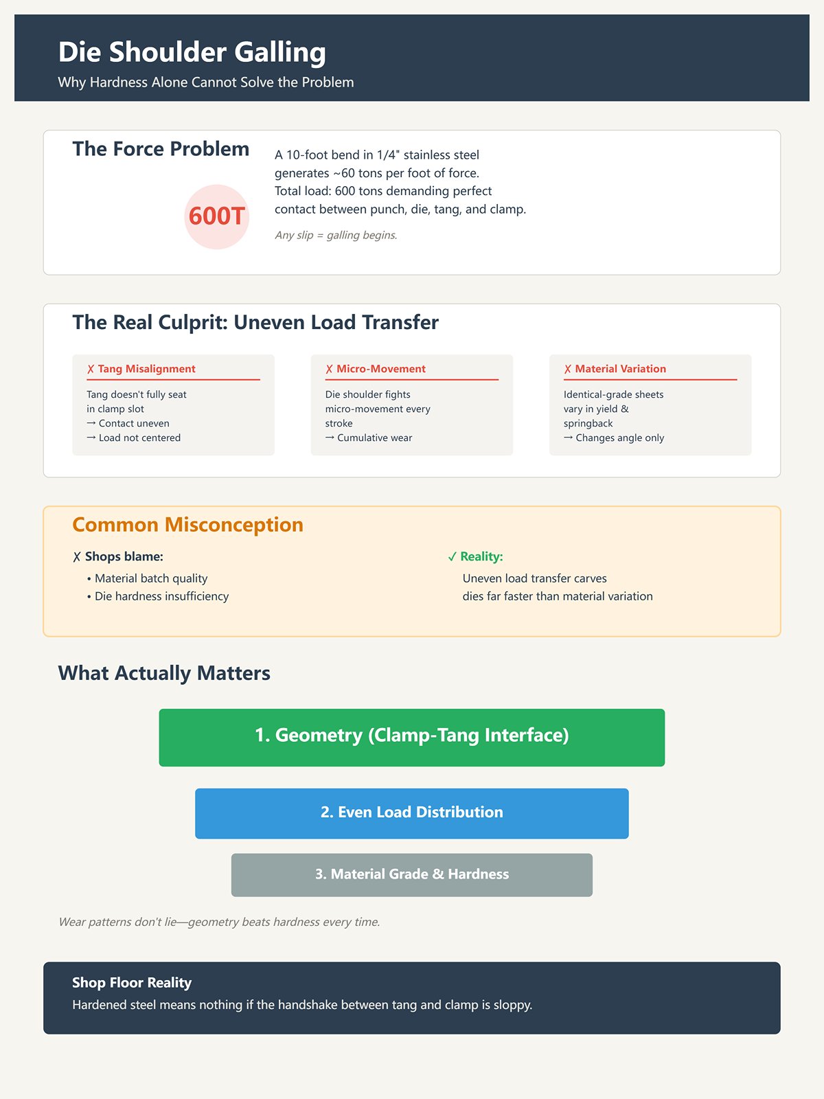
Picture a 10-foot bend in 1/4-inch stainless. Call it roughly 60 tons per foot. That’s 600 tons asking your punch, die, tang, and clamp to shake hands without slipping.
Now imagine that force traveling through a tang that doesn’t fully seat in the machine’s clamping slot. Contact isn’t even. Load isn’t centered. The die shoulder isn’t just resisting vertical force; it’s fighting micro-movement every stroke.
Galling starts at the shoulder, but the argument began up at the clamp.
I’ve seen shops blame material batches, even though identical-grade sheets vary in yield and springback. That variation changes angle, sure. But it doesn’t carve up a die that fast. Uneven load transfer does.
Hardened steel means nothing if the handshake between tang and clamp is sloppy.
Shop Floor Reality: Wear patterns don’t lie—geometry beats hardness every time.
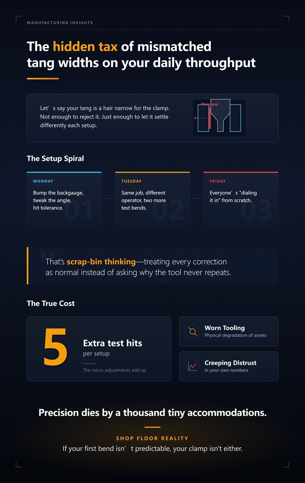
Let’s say your tang is a hair narrow for the clamp. Not enough to reject it. Just enough to let it settle differently each setup.
Monday morning, you bump the backgauge, tweak the angle, hit tolerance. Tuesday, same job, different operator, two more test bends. By Friday, everyone’s “dialing it in” from scratch.
That’s scrap-bin thinking—treating every correction as normal instead of asking why the tool never repeats.
The tax isn’t just worn tooling. It’s the five extra test hits per setup. The micro-adjustments. The creeping distrust in your own numbers.
Precision dies by a thousand tiny accommodations.
Shop Floor Reality: If your first bend isn’t predictable, your clamp isn’t either.
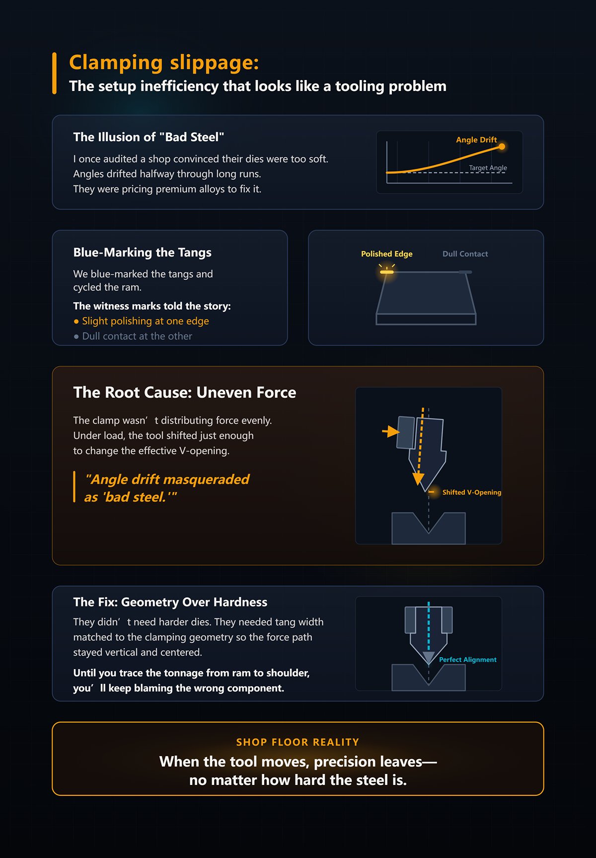
I once audited a shop convinced their dies were too soft. Angles drifted halfway through long runs. They were pricing premium alloys to fix it.
We blue-marked the tangs and cycled the ram.
The witness marks told the story—slight polishing at one edge, dull contact at the other. The clamp wasn’t distributing force evenly. Under load, the tool shifted just enough to change the effective V-opening.
Angle drift masqueraded as “bad steel.”
They didn’t need harder dies. They needed tang width matched to the clamping geometry so the force path stayed vertical and centered.
Until you trace the tonnage from ram to shoulder, you’ll keep blaming the wrong component.
Shop Floor Reality: When the tool moves, precision leaves—no matter how hard the steel is.
You’re asking the right question now: if hardness isn’t the fix, what geometric standards actually keep force centered and repeatable?
Last month I had a shop running three tooling styles in one 12-foot brake. One punch had a 0.500-inch tang. Another was 13 mm. The premium set was 20 mm. All of them “fit” the clamp. None of them shared the same grip geometry. The operator swore the machine was good for ±0.5°. On paper, he was right. On the floor, every changeover meant two or three extra hits to chase angle.
That’s not steel. That’s a three-point mechanical handshake failing — machine clamp, tooling tang, and material tensile strength. When those three don’t grip evenly, your precision ceiling drops long before the machine spec does.
Here’s the mechanism.
Picture 1/4-inch stainless again. Call it 60 tons per foot. Over 10 feet, that’s 600 tons asking the tang to stay perfectly seated while the die shoulder resists spread. If your clamp pocket is built around a 20 mm tang and you slide in a 12.7 mm tang with a filler key, you’ve just reduced contact width by over 7 mm. The force path narrows. Pressure spikes. Micro-tilt becomes possible.
It doesn’t look dramatic. It shows up as angle drift, radius inconsistency, and shoulder wear.
Your machine might promise ±0.5° all day. But your geometry decides whether you ever reach it.
Shop Floor Reality: Your precision ceiling is set by contact area, not catalog hardness.
Let me give you a specific scene.
A shop swaps from a 13 mm tang system to a 20 mm tang system on the same brake. No clamp retrofit. Just adapters. The difference is 7 mm in grip width. The punch seats, clamps, and runs.
First job: 3 mm mild steel, air bend, 8x thickness V-opening. Angles look fine after setup. Mid-run, the inside radius starts creeping tighter by a few hundredths. Not visible to the eye. Measurable on the parts stacking up on the cart.
Why?
Because the narrower tang concentrates clamping force closer to center. Under load, the punch body experiences slightly more elastic rotation — we’re talking microns — but that rotation shifts the effective bend line relative to the V-opening. When the bend line shifts, the neutral axis shifts. Your inside radius follows.
Five millimeters doesn’t sit there politely. It changes how force enters the tool.
And when you’re running 60 tons per foot, that means every foot is amplifying that misalignment. Over a long tool length, those microns add up to angle and radius variation you’ll chase with backgauge tweaks instead of fixing at the clamp.
Scrap-bin thinking says, “Just bump the depth.” Professional thinking asks, “Why did the bend line move in the first place?”
Shop Floor Reality: If tang width changes, your bend line moves — whether you admit it or not.
I carry layout dye for a reason.
We coat the tang, clamp it, cycle under light load, then pull it. The witness marks tell the truth. On mismatched systems, I see heavy polish on one edge, faint contact on the other. That means the clamping pressure isn’t uniform across the tang width.
Pressure equals force divided by area. Shrink the effective area with a mismatched tang, and local pressure climbs. High local pressure digs in. Low-pressure zones allow micro-slip. Now imagine that force traveling through a tang that doesn’t fully seat in the machine’s clamping slot. The load path is no longer vertical. It’s biased.
Under full bending load — again, 60 tons per foot — that bias translates into tiny lateral shifts. Lateral shifts change the effective V-opening at the contact point. Change the V-opening, and you change bend angle for the same ram depth.
No one measures clamping pressure distribution during setup. They measure angle after it’s wrong.
And here’s where machine specs confuse you. Yes, with dynamic crowning and laser feedback, some brakes can hold tighter than ±0.1°. But that control system is correcting symptoms. It cannot stiffen a tang that’s rocking inside an oversized clamp pocket.
You can’t servo your way out of a bad handshake.
Shop Floor Reality: Uneven clamp pressure turns every stroke into a slightly different tool.
Now stack segmented punches across 8 feet.
One segment is 0.02 mm taller than its neighbor. That’s within many manufacturers’ tolerance. Alone, it’s nothing. But pair that with uneven clamping from a tang mismatch, and the taller segment becomes the primary load taker.
Under load, that segment sees more than its share of the 60 tons per foot. It deflects more. The adjacent segment deflects less. Your bend angle varies along the length — tight on one side, open on the other.
Operators call it crowning error. Or material variation. But it doesn’t carve up a die that fast.
The mechanism is simple: uneven clamping exaggerates small height differences. Those differences redirect load. Redirected load changes local penetration into the V-die. Local penetration changes angle and inside radius.
Run 500 parts like that, and the high segment shows premature wear. Now you’re back to blaming steel hardness.
You see how this compounds? Tang width affects pressure distribution. Pressure distribution amplifies height variance. Height variance alters load sharing. Load sharing changes bend geometry.
That’s your precision ceiling.
Next question is obvious: if different tooling systems use 12.7 mm, 13 mm, or 20 mm tangs, how does each design control this handshake differently — and which one actually protects your force path instead of gambling on it?
Shop Floor Reality: At production volume, 0.02 mm plus bad clamping equals a pallet of scrap.
Picture three punches on the bench: a 12.7 mm American safety tang, a 13 mm European Promecam tang, and a 20 mm Wila tang. Same brake. Same 3 mm mild steel. Same 8× thickness V-opening. The only thing that changes is how the tang fills the clamp pocket.
Now load it to 60 tons per foot.
On paper, 12.7 versus 13 mm looks trivial. In steel under load, that 0.3 mm decides whether the tang contacts across its full face or kisses one edge first. The 20 mm tang doesn’t just widen the grip; it changes where the clamping bolts drive force into the punch body. Wider tang means a longer moment arm resisting rotation. Narrower tang means higher local pressure and a greater tendency to rock when the force path isn’t perfectly centered.
That’s not brand loyalty. That’s geometry.
Each system is a mechanical contract: machine clamp geometry, tang width and profile, and the tensile strength of the material you’re bending. Break that contract and the bend line drifts. Keep it coherent and the load path stays vertical.
The question isn’t which system is “best.” It’s which one matches your machine’s constraints without introducing a hidden hinge at the clamp.
I walked into a shop running 1/4-inch plate on an older mechanical brake. American-style tooling. 12.7 mm safety tang. Manual set screws. The operator liked it because it won’t fall out when the clamp loosens.
Fair enough.
But under 60 tons per foot on a heavy air bend, we blued the tang and cycled it. Witness marks showed heavy polish along the front edge, faint contact at the rear. The safety lip kept the punch from dropping, but the actual clamping contact was narrower than the tang width suggested. That creates a pressure spike near the front face.
Pressure equals force divided by area. Same tonnage, smaller effective contact band, higher local pressure. Higher pressure increases bite at one edge and invites micro-rotation toward the die. That rotation shifts the bend line forward a hair. On thin material you chase it with depth. On thick, high-tensile stock, it shows up as angle inconsistency along the length.
The safety tang does what it was designed to do: protect the operator and work with simpler clamps. It was never designed to self-center under high dynamic load. When you ask it to behave like a precision-ground, self-seating system, you’re practicing scrap-bin thinking.
Shop Floor Reality: American tooling is stable in the right clamp, but it won’t fix a force path your machine never controlled to begin with.
Different shop. CNC hydraulic brake with side-loading clamps built for 13 mm Promecam tangs. No safety lip. The tang fills the slot more completely than the 12.7 mm American, and the clamp face typically engages more of the vertical surface.
Under the same 60 tons per foot, the bluing tells a different story: broader, more even contact. Less edge bias. The tang seats deeper and more squarely because the clamp geometry was built around that 13 mm profile. That reduces rotational freedom before full load even hits.
But it doesn’t self-seat. You still align segments. You still tighten in sequence. Setup takes longer than a true quick-change system. That’s the trade-off: moderate setup time for high repeatability at a sane tooling cost.
Here’s where people get confused. They assume Wila-level precision requires Wila-level hardware. Not always. If your production volume is low to medium and you’re not swapping tools ten times a shift, a properly matched Promecam system can deliver “high” precision without the capital hit. The contract is intact because machine and tang were designed together.
Where shops go wrong is forcing a 13 mm tang into a clamp bored sloppy from years of American tooling. Now the tang floats inside a worn pocket, and all the theoretical precision evaporates.
Shop Floor Reality: European precision only exists when the clamp was born European too.
Now look at a 20 mm Wila tang in a hydraulic self-seating clamp. Drop it in, hit the button, and the system pulls the tang up and back into a fixed reference. No set screws. No side loading. The geometry forces alignment before tonnage builds.
Under 60 tons per foot, that wider tang spreads clamping force over a larger face and increases resistance to rotation simply by geometry. More contact width means lower local pressure for the same load. Lower pressure means less bite variation, less micro-slip, and more consistent bend-line position along the length.
But here’s the part salesmen skip.
If you’re running short batches, two setups a day, mild steel under 1/8 inch, you won’t recover the time savings quickly. The precision gain over a well-maintained Promecam system may be measurable, but not profitable. The ROI flips when you’re doing frequent changeovers, segmented tooling across long beds, or high-tensile material where clamping stability protects both angle and tool life.
I’ve seen shops bolt 20 mm tooling into hybrid adapters on 13 mm clamps to “get the best of both.” What they actually get is a stacked tolerance chain and a new hinge point between adapter and ram. Now imagine that force traveling through a tang that doesn’t fully seat in the machine’s clamping slot. You’ve just reintroduced the very rotation the 20 mm system was designed to eliminate.
That’s not upgrading. That’s geometry denial.
Wila isn’t magic. It’s a complete mechanical handshake. Break one finger of that handshake with adapters or worn clamps, and you’re back to chasing microns with ram depth.
Shop Floor Reality: The 20 mm system pays when your volume and tensile loads demand repeatable self-alignment — otherwise you’re buying speed you don’t use.
And that leaves the uncomfortable question: if each system only works as a coherent set, what happens when you start mixing them on the same floor?
| System | Key Points |
|---|---|
| American Tooling (12.7 mm Safety Tang) | Designed to prevent the punch from falling when the clamp loosens; works with simpler clamps; under high load (60 tons/ft), contact area is narrower than tang width suggests; creates pressure spikes near the front edge; increased local pressure leads to micro-rotation and bend-line shift; suitable for safety and basic stability but not for precision self-centering under dynamic load; stable only if the clamp properly controls the force path. |
| European Promecam (13 mm Tang) | Tang fills the slot more completely than 12.7 mm American style; broader and more even clamping contact under load; reduced edge bias and rotational freedom; requires manual alignment and sequential tightening; moderate setup time with high repeatability; cost-effective precision for low-to-medium production; precision depends on a properly matched European clamp—worn or mismatched clamps negate benefits. |
| Wila 20 mm Tang System | Hydraulic self-seating clamp pulls tang into fixed reference automatically; wider tang distributes force over larger contact area; reduced local pressure, micro-slip, and bend-line variation; ideal for frequent changeovers, segmented tooling, long beds, and high-tensile materials; ROI depends on production volume and setup frequency; adapters or hybrid setups introduce tolerance stacking and rotation, negating system advantages; effective only as a complete, integrated system. |
You want to know what actually happens when American, European, and 20 mm systems share the same shop floor?
Angle drift that shows up only on the last three parts of a long run. Tool marks that weren’t there yesterday. Operators bumping depth a hair every ten cycles because “the material must be changing.” Setup times that grow quietly while everyone blames the print.
None of that starts in the steel.
It starts in the handshake.
When you stack an adapter between ram and punch, you’re not just changing tang width. You’re inserting a new surface, a new tolerance band, a new load path. The machine clamps the adapter, the adapter holds the tool, and the material pushes back through both. That’s no longer a three-point mechanical handshake. It’s four fingers, and one of them is numb.
At 60 tons per foot on a long air bend, that extra interface sees the same force as the tang. Same force. Smaller, imperfect contact. Pressure spikes where surfaces aren’t perfectly flat, and the adapter becomes a hinge you never designed.
That’s scrap-bin thinking dressed up as flexibility.
The illusion is simple: “If the tang doesn’t match, we’ll just adapt it.” The reality is more subtle. Every added layer moves your reference surface farther from the ram. You’ve increased the moment arm, however slightly, which increases the rotational leverage under load. Microns at the clamp become thousandths at the bend line.
You don’t see it on day one.
Two weeks in service, you start chasing it with depth corrections.
Shop Floor Reality: Adapters don’t blend systems — they dilute the geometry that made each one precise.
You can make parts.
That’s not the same as holding tolerance.
A 13 mm European tang in a clamp designed around a 12.7 mm American safety profile doesn’t fail dramatically. It fails quietly. The clamp face doesn’t engage the groove the way it was designed to, so the tang seats on partial contact. Under light load, it behaves. Under 60 tons per foot, the contact band shifts forward and the tang tries to rotate into the die.
Now imagine that force traveling through a tang that doesn’t fully seat in the machine’s clamping slot.
You’ve created a pivot point.
Some shops get away with it. They add custom shims, grind offsets, tweak punch heights, and claim ±0.005 inch all day. I’ve audited those shops. The ones succeeding are not relying on the adapter for precision. They’re compensating everywhere else — controlled tonnage, consistent material batches, disciplined setup sequencing. They’ve built a process cage around a geometric compromise.
That’s management discipline, not adapter magic.
The problem is repeatability across shifts, operators, and materials. The European system was built for side clamping pressure into a groove. The American clamp was built for a safety tang bearing vertically with set-screw compression. When you mix them, the load path is neither fully vertical nor fully lateral. It’s diagonal and inconsistent along the bed, especially on worn clamps.
And worn clamps are the rule, not the exception.
So yes, you can run European dies on an American brake. You just won’t be running a true European geometry anymore. You’ll be running a hybrid that depends on constant babysitting.
Shop Floor Reality: If precision depends on the operator “knowing the trick,” the system itself isn’t precise.
Let’s slow this down.
An adapter adds at least two new interfaces: ram-to-adapter and adapter-to-tool. Each interface has flatness tolerance, parallelism tolerance, and clamping compliance. Add them together and you’ve created a tolerance stack that lives above your bend line but expresses itself in the angle.
It doesn’t disappear. It relocates.
Picture a 20 mm self-seating tool mounted into a 13 mm-style adapter, then clamped in a non-self-seating system. The original 20 mm concept spreads load across a wider tang and pulls up and back into a fixed reference. The adapter interrupts that pull-back motion. The clamp now grabs the adapter body, not the precision-ground tang face.
You’ve just moved the reference surface one layer away from the ram.
Under load, micro-deflection happens at the weakest compliance point. That’s usually the thinnest section of the adapter or the least-supported face. The tang might be hardened to HRC 60, the sheet metal at HRC 15, but hardness doesn’t stop rotation if the load path is crooked. In fact, harder tooling concentrates pressure at imperfect contacts, which accelerates fretting at those adapter faces.
The lost precision goes into elastic flex at each interface.
It shows up as angle variation along length because deflection isn’t uniform. It shows up as increased tool wear because pressure isn’t evenly distributed. It shows up as setup creep because operators compensate with depth instead of fixing geometry.
And once you start stacking adapters to make “one set fit all machines,” you’re not standardizing. You’re multiplying tolerance chains.
This is where the illusion finally cracks.
Precision isn’t a property of the tool alone. It’s a property of the entire load path from ram to material and back. Break that path with layered compromises, and no brand stamp will save you.
Shop Floor Reality: Every adapter you add is another place for force to bend something you never intended to bend.
You want a stable, precision-focused system?
Start with a simple scene. Quarter-inch mild steel, 10-foot bend, V-die opening at 2 inches. Using the standard air-bend estimate, you’re around 60 tons per foot. The machine hums. Angles repeat. Tools last.
Now swap that sheet for high-tensile at the same thickness and keep the same die opening because “steel is steel.” Your tonnage requirement doesn’t creep up politely — it jumps. Yield strength climbs, springback stretches to 8–10 degrees, and the brake answers by pushing harder. Same geometry. Different resistance. The load path we just cleaned up with proper tang-to-clamp fit now carries force it was never proportioned for.
This is where the disconnect lives.
We’ve been blaming adapters for corrupting geometry — correctly. But even a perfect, uninterrupted load path will lose precision if the die shape and punch radius were chosen for mild steel and then forced onto high-tensile material. The machine will deliver whatever force is required within its limits. The tooling absorbs the consequences.
When your die opening shrinks to “control” springback on high-tensile, tonnage rises fast. Not linearly. Fast. Shops see tighter V equals tighter control. What they get is exponential force demand, frame deflection, and localized tool stress that no tang width can stabilize.
The press brake always wins.
The tooling always loses.
Shop Floor Reality: If your die chart is built around mild steel, high-tensile will expose it in a week.
I walked into a shop running hardened 28–32 HRC dies on structural-grade mild steel for years. Clean bends. Minimal marking. Same dies were kept on the rack when they took on a contract in high-strength low-alloy.
Two weeks in service, the shoulders of the V were brinelled — tiny dents where the material bit into the die edge under higher contact pressure. Not dramatic cracks. Just witness marks that grew. Angles started drifting along the bed.
They blamed “soft tooling.”
But it doesn’t carve up a die that fast unless something else changed.
Here’s the mechanism. High-tensile resists yielding, so the sheet doesn’t flow into the V the way mild steel does. Contact pressure concentrates along narrower bands at the die shoulders. If your die hardness and edge treatment were chosen assuming lower yield material, those shoulders now see higher localized stress cycles. Multiply that by length.
On a long air bend at 60 tons per foot, that force distributes along the V shoulders. Increase material yield and keep the same opening, and you increase the contact stress at those lines of contact. Hardness is not about ego; it’s about resisting plastic deformation at those contact zones.
And here’s the trap: even within “the same” grade, yield strength varies batch to batch. I’ve seen coils labeled identically that spring back differently across shifts. If your die hardness margin is thin, those variations show up as tool wear and angle inconsistency you can’t explain.
Material variability doesn’t excuse bad geometry — it punishes it.
Shop Floor Reality: If your die shoulders are denting, your hardness spec was written for yesterday’s material.
Picture a 1/8-inch high-tensile blank and a sharp punch tip radius selected to “lock in” a crisp 90. It works on mild steel because the material yields and wraps predictably around the tip.
High-tensile doesn’t wrap. It resists, stores energy, then springs back harder.
So the operator dials in more depth to compensate. The ram pushes deeper into the V, increasing tonnage and driving the sheet tighter against the die shoulders. You’ve just increased both contact pressure and required force because the punch radius is too small for the material’s natural bend radius.
Now imagine that force traveling through a tang that doesn’t fully seat in the machine’s clamping slot.
Even with a perfect clamp, the mismatch between punch radius and material yield means you are forcing the inner fibers past their comfortable strain. Micro-cracking on the inside of the bend. Surface galling on coated stock. Accelerated punch tip wear because the contact patch is narrower and hotter.
The irony? A slightly larger punch radius often reduces required tonnage and stabilizes springback because it allows the material to form closer to its natural radius instead of fighting it.
But scrap-bin thinking says sharper is more precise.
Precision is not sharpness. It’s controlled strain.
Shop Floor Reality: If you’re chasing springback with ram depth instead of radius selection, you’re bending the tool more than the part.
I’ve seen shops swear they air bend everything — until high-tensile shows up. Suddenly they’re bottoming “just on this job” to beat springback.
Let’s run a clean example. Take that same 1/4-inch plate, 2-inch V, air bending at roughly 60 tons per foot. Switch to bottoming with a tight V to control angle. Tonnage doesn’t nudge upward. It can double or triple depending on opening and material strength because you’re now forcing the sheet to conform fully to the die angle.
And that force doesn’t just travel into the material. It travels into the frame, the bed, the ram guides. Frame rigidity becomes the hidden variable. A machine that held ±0.5 degrees air bending may drift when bottoming high-tensile simply because the frame deflects under peak load.
You start blaming tooling again.
But the forming method was dictated by die geometry that didn’t respect material behavior. Instead of selecting a die opening and punch radius that allow controlled air bending of high-tensile, the shop defaulted to bottoming to mask springback. That decision multiplied force, amplified frame deflection, and magnified every microscopic compliance in the load path we just worked so hard to clean up.
Air bending, bottoming, coining — they are not style choices. They are force strategies.
And when tooling style accidentally forces you into a higher-force strategy than your machine was built for, precision becomes a negotiation with physics you won’t win.
Shop Floor Reality: If your forming method changes because the material got stronger, your tooling system wasn’t designed as a system.
You’re asking the right question now: how do you select die opening, punch radius, hardness, and forming method for high-tensile without losing precision or overloading the machine?
Stop picking parts in isolation. Start mapping the three-point handshake — machine clamp, tooling tang, material tensile — and let that map tell you where the real bottleneck lives.
Precision isn’t a property of steel. It’s a property of compatibility.
Shop Floor Reality: If you’re still shopping tooling by brand instead of by load path, you’re guessing.
Begin with the machine, not the material. What is the rated tonnage per foot? What clamping style? What tang width was that clamp designed to bear against without point loading?
If your brake is rated for 60 tons per foot in air bending, that number assumes full seating of the tang and uniform pressure distribution across the clamp face. Now imagine a tang that is 0.020 inches narrower than the slot, or an adapter stack adding another interface. That 60 tons per foot no longer travels as a flat handshake. It concentrates.
You’ve seen the bluing marks. Heavy at the ends. Light in the middle.
Cross-style mixing can work. A 0.500-inch precision tang running in a compatible clamp with full contact and proper seating can behave perfectly, even if the die below follows a different standard. The success stories aren’t accidents — they work because the load path stays continuous and the bearing surfaces match in width and hardness.
But when shops assume “it fits” equals “it’s compatible,” that’s scrap-bin thinking.
Next, map the material. High-tensile with 3°–5° springback on mild steel can jump beyond that, and CNC compensation only works if the punch angle and radius are chosen to under-bend predictably. A larger punch radius that respects the material’s natural inside radius often reduces required depth and stabilizes springback, keeping you in air bending instead of drifting into bottoming.
Die opening then becomes a force governor. Open it too tight and tonnage climbs. Open it appropriately and you control strain without exceeding machine deflection limits.
Hardness? Choose it based on contact stress, not ego. If localized shoulder pressure rises with higher yield strength, your die needs enough hardness to resist brinelling under that exact load — not under last year’s mild steel.
This isn’t a tooling list. It’s a compatibility matrix: machine clamp geometry → tang width and bearing area → die opening and punch radius → material tensile and springback → forming method as a force strategy.
Miss one link and the others pay for it.
Shop Floor Reality: If your forming method changes just to survive a material change, your matrix was never aligned.
Premium steel is not a badge. It’s insurance against a specific failure mode.
Take a hypothetical: 1/4-inch high-tensile over a 2-inch V at roughly 60 tons per foot. That force translates into high line contact at the die shoulders. If your die steel cannot be heat-treated into a hardness range that resists that localized pressure, you will see brinelling and angle drift long before dimensional wear shows up.
In that case, quenchable alloy tooling earns its keep. Not because it’s premium — because the contact stress demands it.
Now flip it. If your machine cannot deliver uniform pressure across the tang because the clamp face is worn or the tang width is mismatched, buying harder steel doesn’t solve uneven loading. It simply moves the deformation into the clamp, the ram, or the part. You’ll brag about tool hardness while chasing inconsistent angles.
That’s how cost-per-bend analysis lies to you. It counts tool life but ignores load distribution.
Budget tooling suffices when three conditions are true: material yield is moderate, die opening keeps tonnage well within machine limits, and the clamp-to-tang interface is fully seated and rigid. Under those conditions, you’re not asking the steel to survive abuse.
Premium tooling is justified when contact stress, cycle volume, or material hardness push the shoulder and punch tip into plastic-risk territory.
If you don’t know which regime you’re in, you’re not doing analysis. You’re shopping.
Shop Floor Reality: Buy hardness only after you’ve bought compatibility.
Here’s the part nobody wants to admit.
Many shops blame tooling cost when their real bottleneck is setup variability. Different tang standards. Adapters in one bay, direct clamp in another. Operators shimming to “make it run.”
At 60 tons per foot, every extra interface is another compliance point. Another chance for microscopic rotation. Another variable the operator compensates for with ram depth instead of geometry.
Quick-change clamping with matched tang standards reduces that variability. Not because it’s fancy — because it preserves the load path and repeatability. Faster setups are a side effect of mechanical consistency.
But if your volume is low-mix, long-run, and your existing tooling seats perfectly with uniform witness marks, pouring money into a new system for speed alone may not move the needle. Your bottleneck might be programming, material handling, or inspection.
This is where the compatibility matrix becomes a management tool. Ask three blunt questions:
Where is force entering the system? Where is it concentrating? Where is it escaping as deflection or variability?
Answer those before you sign a tooling purchase order.
The one thing you should carry forward is this: precision is not purchased in steel grades or clamp brands — it is engineered at the intersection of clamp geometry, tang width, die opening, punch radius, material tensile, and forming method. That intersection is invisible until high-tensile exposes it.
Most shops never see it because mild steel forgives them.
High-tensile doesn’t.
Shop Floor Reality: Stop buying steel. Start buying a load path that makes sense.


