

Last spring I had a kid run a 10-foot stick of 14-gauge stainless straight into the die like he was stomping grapes. Ram down. Hard stop. He figured more pressure meant a tighter bend.
What he got was a 92-degree part on a print calling for 90. On stainless, that’s scrap.
He thought the machine’s job was to push. It isn’t.
Stand in front of a press brake while it cycles. The upper tool (the punch) comes down into a V-shaped lower die. The sheet doesn’t fold because it was “squeezed.” It bends because force is delivered at a specific depth, against a specific opening, with a specific amount of springback (the metal’s tendency to relax after you release pressure).
Change the force, the tooling, or the depth by a hair, and the angle changes.
Look at it this way: a torque wrench doesn’t “tighten bolts.” It delivers a calibrated amount of torque. A press brake doesn’t “bend metal.” It delivers calibrated force so the metal reaches a target angle.
Miss that, and you’re not operating a machine—you’re gambling with steel.
The cognitive shift I want you to make is simple: stop thinking about motion (ram going down) and start thinking about outcome (angle achieved).
The word “brake” doesn’t come from car brakes. It comes from an old term for bending sheet metal—“braking” meant folding along a straight line.
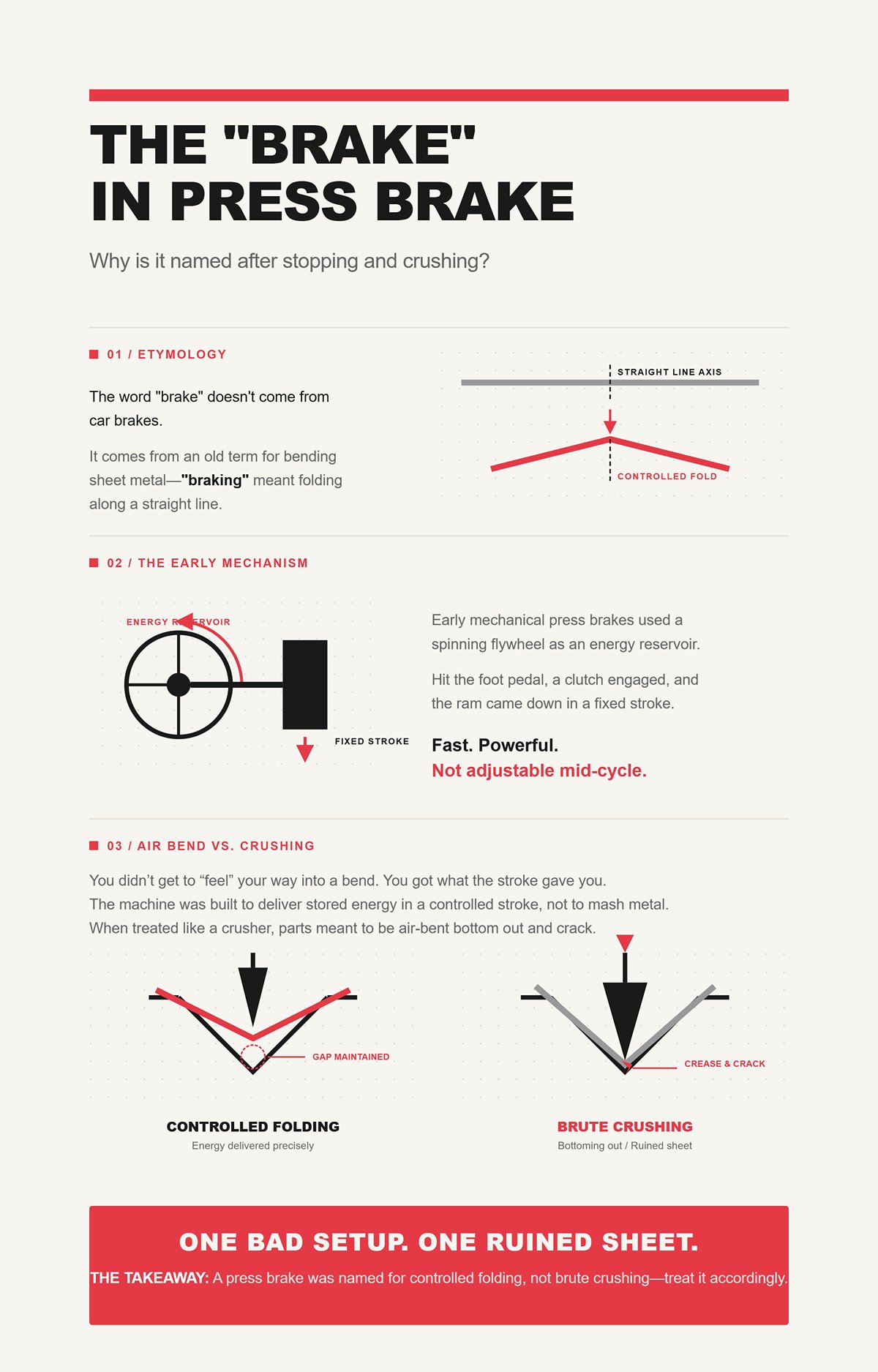
Early mechanical press brakes used a spinning flywheel as an energy reservoir. Hit the foot pedal, a clutch engaged, and the ram came down in a fixed stroke. Fast. Powerful. Not adjustable mid-cycle.
You didn’t get to “feel” your way into a bend. You got what the stroke gave you.
That design tells you something. The machine was built to deliver stored energy in a controlled stroke, not to mash metal until it looked right. When apprentices treat it like a crusher, they bottom out parts that were meant to be air-bent—and suddenly that 4×8 sheet has a shiny crease line that will crack on the next forming step.
One bad setup. One ruined sheet.
The name stuck, but the meaning drifted. “Brake” was always about controlled folding, not smashing.
The Takeaway: A press brake was named for controlled folding, not brute crushing—treat it accordingly.
“Press” makes people think the job is to apply force until the metal submits.
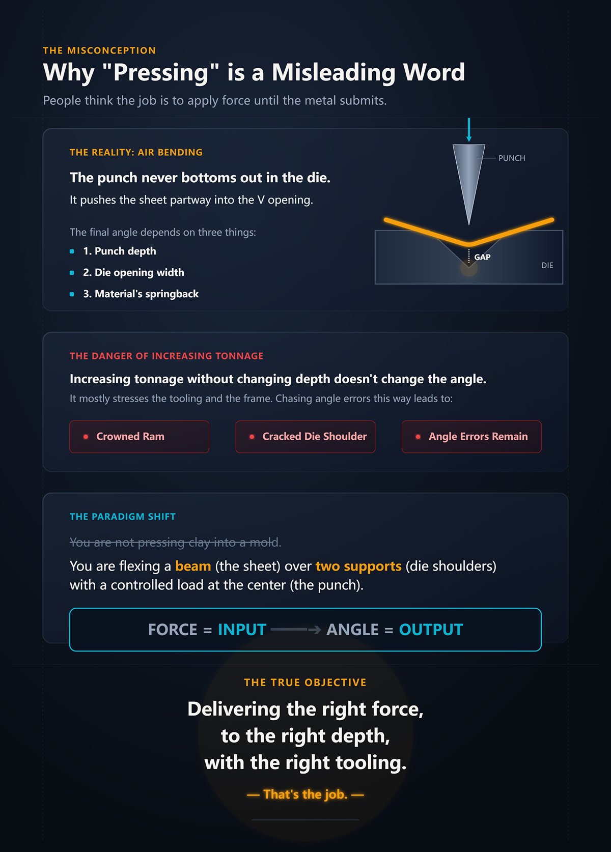
But in air bending—the most common method—the punch never bottoms out in the die. It pushes the sheet partway into the V opening. The final angle depends on three things: punch depth, die opening width, and the material’s springback.
If you increase tonnage without changing depth, you don’t magically get a different angle. You mostly stress the tooling and the frame. I’ve seen guys chase angle errors by cranking tonnage, and the only thing they achieved was a crowned ram and a cracked die shoulder.
Look at it this way: you’re not pressing clay into a mold. You’re flexing a beam (the sheet) over two supports (the die shoulders) with a controlled load at the center (the punch). That’s basic mechanics of materials.
Force is the input. Angle is the output.
When you understand that, “pressing” stops being the goal. Delivering the right force, to the right depth, with the right tooling—that’s the job.
So if it’s not about pushing harder, what exactly are you controlling?
I’ll give you a simple shop example. Same 0.125-inch mild steel. Same punch. Change the lower die from a 1-inch V opening to a 1.5-inch V opening. Run the exact same programmed depth.
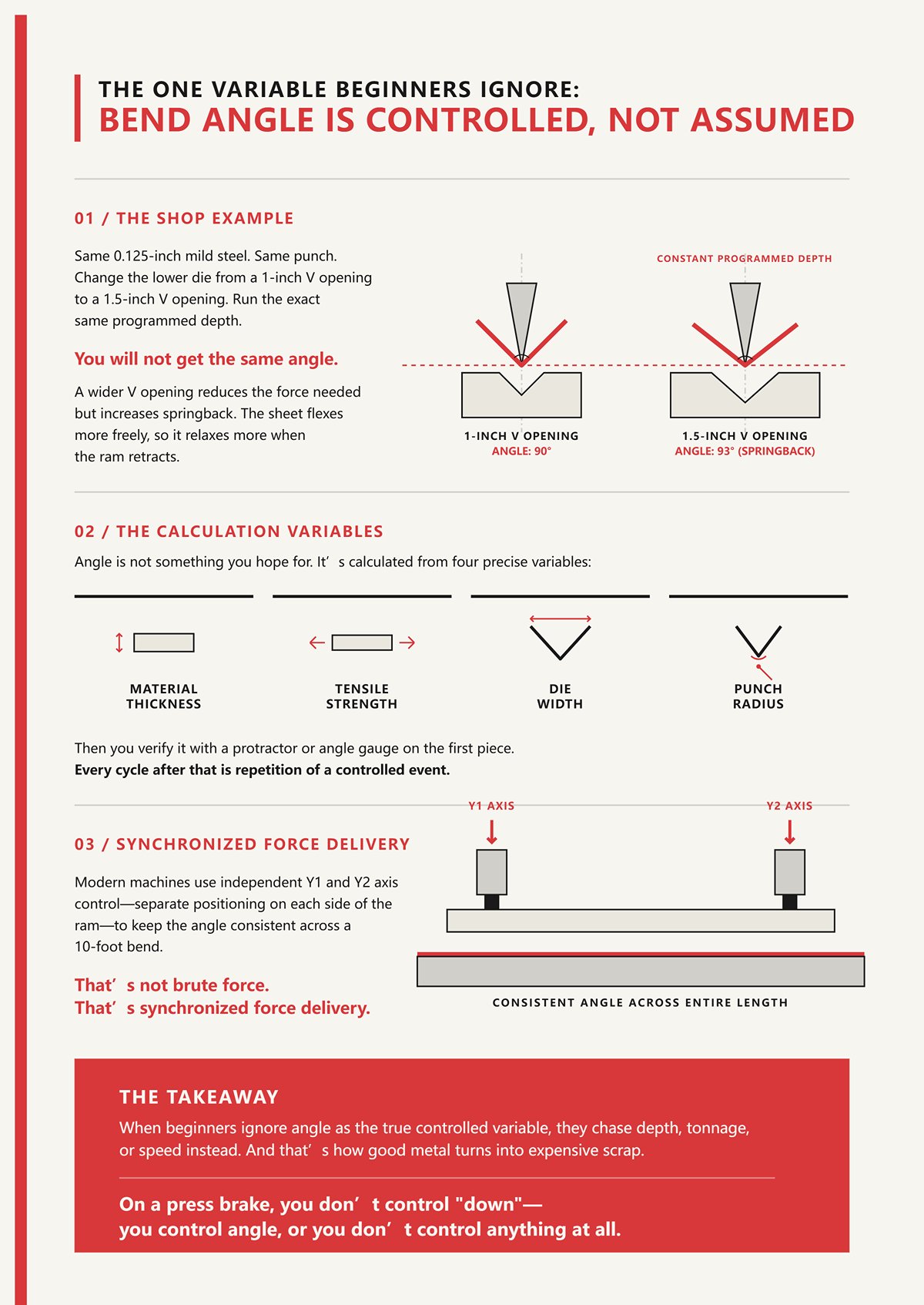
You will not get the same angle.
A wider V opening reduces the force needed but increases springback. The sheet flexes more freely, so it relaxes more when the ram retracts. If you didn’t calculate that, you’re holding a 93-degree part in your hand wondering what happened.
Angle is not something you hope for. It’s something you calculate from material thickness, tensile strength, die width, and punch radius. Then you verify it with a protractor or angle gauge on the first piece. Every cycle after that is repetition of a controlled event.
Modern machines even use independent Y1 and Y2 axis control—separate positioning on each side of the ram—to keep the angle consistent across a 10-foot bend. That’s not brute force. That’s synchronized force delivery.
When beginners ignore angle as the true controlled variable, they chase depth, tonnage, or speed instead. And that’s how good metal turns into expensive scrap.
The Takeaway: On a press brake, you don’t control “down”—you control angle, or you don’t control anything at all.
You’ve got a print calling for a 90-degree flange, 2.000 inches from edge to bend line, on 0.125-inch mild steel. You’ve already picked your punch and a 1-inch V-die. You know the material thickness. You know the tensile range. So how do you set the machine so the first part isn’t a guess?
You don’t start with “how far down.” You start with bend deduction and target angle. The CNC control uses the die opening and material data to calculate a theoretical depth that should yield 90 degrees after springback. That depth isn’t arbitrary—it’s tied to geometry. Change the die width or material strength, and the calculated depth changes with it.
Then the cycle begins.
Every bend is a stack of controlled events: position, clamp, descend, form, springback, release. Miss any layer and the math you trusted at the screen falls apart at the tooling.
Let’s follow one sheet through it.
Slide that sheet onto the bed and push it back until it touches the fingers of the CNC backgauge. Those fingers aren’t just stops. They’re servo-driven positioning devices, usually accurate to a few thousandths of an inch.
If your flange is supposed to be 2.000 inches, and your backgauge is off by 0.020, your bend line moves 0.020. The angle could be perfect and the part still fails inspection because the leg length is wrong. Beginners blame the bend. It was the position.
Look at it this way: the press brake forms an angle along a line in space. The backgauge decides where that line exists. If the line is wrong, everything after it is perfectly wrong.
Now add another layer. Modern brakes use two independent axes—Y1 and Y2—controlling the left and right sides of the ram. If they’re even slightly out of sync, one side of the punch hits first. Across a 10-foot part, that becomes a tapered angle—89 degrees on one end, 91 on the other. The backgauge assumed the ram would stay parallel. If the machine isn’t calibrated, your “accurate” position feeds a twisted bend.
One calibration drift. One batch of panels that won’t sit flat in assembly.
The backgauge doesn’t bend metal. It decides where the physics will happen.
The Takeaway: If the bend line isn’t exactly where you think it is, angle accuracy won’t save the part.
You hit cycle start. The ram moves down fast at first—approach speed. No load yet. Just closing distance.
Then it slows before contact. That slowdown isn’t for drama. It’s for control. The moment the punch touches the sheet, force ramps up fast. Too much speed at contact and the machine overshoots the programmed depth before the control can react.
On a servo-electric brake, that motion is driven by ball screws. They’re precise, efficient, and excellent for thin-to-medium material. But they have torque limits. Push them into heavy plate territory and you hit their ceiling. Hydraulics, on the other hand, can deliver high tonnage all day, but you’re managing fluid compression and valve response instead of direct mechanical drive.
Different drive types, different behavior under load.
And load changes the machine itself. Under high tonnage, the bed and ram deflect slightly. Without crowning—an adjustable compensation that pre-bows the bed—you get what we call the canoe effect: tighter angle at the ends, open in the center. The ram did exactly what it was told in terms of depth. The frame moved anyway.
Speed matters because the control system needs time to measure resistance and stop at the correct forming depth. Too fast, and you blow past the calculated point. Too slow, and you waste cycle time without gaining accuracy.
What’s really happening here isn’t “ram down.” It’s controlled force rising to a calculated threshold, across a structure that flexes under load, compensated in real time.
Miss that balance and you’re not bending—you’re stress-testing the frame with customer material in the die.
The Takeaway: Ram speed isn’t about hurry or caution—it’s about giving the machine time to hit the exact force and depth your angle calculation demands.
The punch reaches programmed depth. On the screen, it says you’ve hit the number that should produce 90 degrees.
You retract the ram.
The part opens to 92.
That’s springback—the metal’s elastic recovery after you remove load. Every material has a yield strength (where it permanently deforms) and an elastic range (where it wants to return). Air bending lives in the balance between the two. You push past yield just enough to get permanent deformation, knowing some elastic recovery will occur.
Mild steel might spring back 1 to 2 degrees in common thicknesses. Stainless can jump 2 to 5 degrees depending on grade and temper. Even within the same grade, different heat lots behave differently. You can run 20 good parts, load a new sheet from a different batch, and suddenly you’re chasing angle again.
So what do we do? We overbend. If we expect 2 degrees of springback, we program for 88 to land at 90 after release. Modern controls can use angle measurement systems to adjust automatically, but the principle doesn’t change: you never get exactly what you formed under load.
This is where the force-delivery idea earns its keep. You’re not forming to a visual target. You’re delivering a calculated overbend based on known material behavior, verifying it on the first piece, then locking it in.
Ignore springback, and your “perfect” depth setting turns into a stack of parts all 2 degrees open. On stainless, that’s scrap.
The Takeaway: Always program for where the metal will end up after it relaxes, not where it sits under the punch.
The ram retracts. The backgauge moves to the next position. You rotate or flip the part for the next bend.
One cycle might take 10 seconds on a small bracket. That sounds trivial until you’re running 3,000 pieces. Shave one second off safely and you save nearly an hour of machine time. Add one second of hesitation or correction, and you pay for it all week.
But here’s the trap: chasing speed before the first piece is right.
If you rush setup, skip the first-piece inspection, or ignore slight angle drift across the bed, you don’t just lose seconds. You lose batches. Production cost doesn’t climb in neat increments—it spikes when you discover 200 parts with a 1-degree error that won’t fit the mating assembly.
Cycle time is cumulative. So is error.
A well-run press brake operation looks almost boring: consistent approach speed, controlled forming speed, verified angle, repeatable backgauge positioning. The machine isn’t straining. The operator isn’t guessing. The numbers on the screen match the geometry in your hand.
That’s not brute force. That’s calibrated repetition.
And once you see the full cycle—position, controlled descent, compensated force, calculated overbend, repeat—you start to notice something: the bending method itself changes how much springback you fight, how much tonnage you need, and how much the frame deflects.
Which raises the next question: if the cycle stays the same, how does changing the bending method change the outcome?
The Takeaway: In production, one second saved the right way builds profit; one degree missed builds scrap.
| Step | Title | Content | Takeaway |
|---|---|---|---|
| Step 1 | Positioning: Why the CNC backgauge is the unsung hero of accuracy | The CNC backgauge positions the sheet with servo-driven fingers accurate to thousandths of an inch. If the backgauge is off, the bend line shifts—even if the angle is perfect—causing part failure due to incorrect leg length. The press brake forms the angle, but the backgauge determines where that angle exists in space. Modern brakes use independent Y1 and Y2 axes; if out of sync, they create tapered angles across long parts. Machine calibration and structural alignment directly affect bend accuracy. The backgauge determines where the physics of bending occur. | If the bend line isn’t exactly where you think it is, angle accuracy won’t save the part. |
| Step 2 | Clamping and Descent: What the ram does and why speed matters here | The ram descends quickly at approach speed, then slows before contact for control. Excess speed at contact can cause overshoot before the control reacts. Servo-electric brakes use ball screws—precise but torque-limited—while hydraulic systems provide high tonnage but manage fluid dynamics. Under load, the bed and ram deflect; crowning compensates for this to prevent uneven angles (the “canoe effect”). Proper speed allows the control system to measure resistance and stop at the correct forming depth. The process is controlled force rising to a calculated threshold across a flexing structure. | Ram speed isn’t about hurry or caution—it’s about giving the machine time to hit the exact force and depth your angle calculation demands. |
| Step 3 | The Springback Dilemma: Why the metal never stays exactly where you put it | After forming and releasing, metal springs back due to elastic recovery. Different materials and batches vary in springback behavior. Operators compensate by overbending based on expected recovery (e.g., programming 88° to achieve 90°). Modern systems may auto-adjust with angle measurement, but the principle remains: you must account for post-load relaxation. Successful bending requires calculated overbend verified on the first piece. | Always program for where the metal will end up after it relaxes, not where it sits under the punch. |
| Step 4 | Release and Repeat: How cycle time compounds into production cost | Each bend cycle includes retracting the ram, repositioning the backgauge, and handling the part. Small time savings compound significantly over large production runs. However, prioritizing speed before validating the first piece risks costly batch errors. Consistency in speed, positioning, and angle verification ensures repeatability. Production efficiency depends on calibrated repetition, not brute force. | In production, one second saved the right way builds profit; one degree missed builds scrap. |
You run the same machine. Same operator. Same sheet. The only thing you swap is the tooling setup and how deep you drive it.
One job takes 40 tons and springs back 2 degrees. Another needs triple the tonnage and barely moves after release. A third hits dead-nuts 90 every time—but the machine groans doing it.
Nothing about the ram cycle changed. What changed was the relationship between punch, die, and material. That relationship is the bending method.
If you don’t know which method you’re actually using, you’re not “forming.” You’re gambling with tonnage, springback, and frame deflection all at once.
Picture a 0.125-inch mild steel sheet sitting over a 1-inch V-die. You bring a standard 88-degree punch down and stop before the punch tip bottoms out in the die.
The sheet only touches at three points: the punch tip and the two die shoulders. It’s literally hanging in the air between them. That’s air bending.
Now change nothing about the punch. Swap the die to a 0.75-inch V. Run the same programmed depth.
You will not get the same angle.
Why? Because in air bending, the inside bend radius forms as a function of the die opening—roughly 16% of the V-opening for mild steel. Narrower V, tighter radius. Tighter radius means the material stretches more on the outside and compresses more on the inside. That changes how far you must overbend to land at 90 after springback.
The punch is pushing down. But the die opening sets the geometry the material is allowed to flow into.
Now push deeper—until the material contacts the die faces fully. You’re no longer floating between three points. The sheet is being pressed into the die angle itself. That’s bottoming. The die angle now physically defines the final bend angle because the material is forced to conform to it under load.
Go deeper still—past simple contact—and you begin plastically deforming the material through the entire thickness at the bend line. That’s coining. You’re not just bending around a radius; you’re compressing the metal into the die cavity and thinning it slightly at the apex.
Look at it this way: the die isn’t just a support block. It’s the boundary condition. It decides how much freedom the metal has to form its own radius versus how much it must obey the tool geometry.
Get that wrong and you’ll chase angles all shift, wondering why the same depth setting gives three different results.
The Takeaway: The die opening and angle define how the material is allowed to deform—depth alone means nothing without that geometry.
On most jobs that roll through my shop—brackets, covers, frames—we air bend. It’s fast. It’s flexible. One punch and a handful of V-dies can handle a wide thickness range.
You want 90 degrees? You don’t need a 90-degree die. You use, say, an 88-degree punch and control depth. Stop higher, you get 100. Go deeper, you get 85. One tool set, infinite angles.
That flexibility is why air bending uses the least tonnage of the three methods. You’re only forming to a radius, not smashing the material into a cavity. Lower tonnage means less frame deflection, less wear, and faster cycles.
But here’s the ceiling.
Because the part only contacts three points, the final angle depends on:
Run a 6-foot part without proper crowning and you’ll see it: 90 at the ends, 92 in the center. The ram hit the programmed depth everywhere. The frame flexed anyway.
Modern CNC brakes with angle sensors can measure and auto-correct in real time. That helps. It does not change the physics. Air bending always leaves you balancing springback against depth control.
I’ve watched a new operator assume the screen number guarantees the angle. What he got was a 92-degree part on a print calling for 90.
The Takeaway: Air bending buys flexibility and low tonnage, but angle accuracy lives and dies on material consistency and machine compensation.
Now take that same 0.125-inch mild steel and put it over a 90-degree die. This time, you drive the punch until the material fully seats against the die faces.
You’re no longer guessing how much springback will open the angle. The die angle is 90. The material is pressed firmly into 90. Springback still exists, but it’s dramatically reduced because more of the cross-section has yielded.
Tonnage jumps—typically several times higher than air bending for the same material and thickness. Why? Because you’re forcing the entire bend zone into conformity with the die walls, not just forming a floating radius.
That higher tonnage means more bed and ram deflection if the machine isn’t built or crowned for it. On a light-duty brake, bottoming thick material can exaggerate the canoe effect instead of fixing angle variation.
But when you match the tooling precisely to the material thickness—and that’s key—bottoming delivers repeatability batch after batch. Less dependence on subtle overbend adjustments. Less sensitivity to small yield variations.
The trade-off? Each material thickness needs its own die pairing. Change thickness, change tooling.
Ignore that and try to bottom thin aluminum in a die meant for thicker steel, and you’ll bruise the bend line beyond spec. That cosmetic damage alone can kill a visible part.
The Takeaway: Bottom bending sacrifices flexibility and demands more tonnage in exchange for reduced springback and tighter angle repeatability.
Coining is where apprentices think they’re being “extra accurate.”
You take a sharp punch—often with a small tip radius—and drive it hard into the material until the metal yields through nearly the full thickness at the bend line. The inside radius becomes almost equal to the punch tip radius. The material is literally compressed and thinned at the apex.
Springback? Minimal. Sometimes less than half a degree.
Sounds perfect.
Now look at the tonnage chart. Coining can require five to ten times the tonnage of air bending for the same material. That force doesn’t disappear. It goes into the frame, the tooling, and the sheet.
On a machine not rated for it, you risk permanent bed deflection. On hardened stainless with a sharp punch, you risk micro-cracking along the bend line. On cosmetic aluminum, you can leave a witness mark that no finishing process will hide.
On stainless, that’s scrap.
Coining absolutely delivers precision when the machine, tooling, and material are matched correctly. It’s common in high-volume parts where angle tolerance is tight and variation is unacceptable.
But it is the least forgiving method. Depth errors aren’t corrected with a tap of the foot pedal. Tool wear shows up in the angle immediately. And the tonnage demand pushes your machine toward its structural limits.
You’re not just bending anymore. You’re cold forging a line into the sheet.
Which leads to the next hard question: if each method changes tonnage demand this dramatically, how sure are you that your machine’s rated capacity actually covers the way you’re bending—not just the thickness on the print?
A kid came into my shop once proud as hell of his new 175‑ton press brake. “Can bend anything we’ll ever need,” he said.
First job he ran was 3/16 stainless, bottom bending, full 10‑foot length. Machine didn’t stall. It groaned. Six months later the bed had a permanent smile in it. Not visible to the eye. Visible in every angle check.
He bought the biggest machine he could afford.
He never asked whether it was the right one.
The question you should be asking is simpler and harder: how do you calculate whether your brake’s rated tonnage actually covers the bending method you’re using—across the full length you plan to bend—without warping the machine that’s supposed to make you money?
Let’s break it down the way I explain it to apprentices who think tonnage is just a bragging number.
Walk up to a tonnage chart and you’ll see something like this: 4 mm mild steel over a 32 mm V‑die requires about 330 kN per meter. That’s not total force. That’s force per meter of bend length.
Already you can see the trap. A 2‑foot bracket and a 10‑foot panel are two completely different loads on the same machine.
Most shops use a formula for air bending mild steel around 60,000 psi tensile strength:
P = 650 × S² × L / V
Where:
That S² term is the part beginners miss. Thickness is squared. Double the thickness and your tonnage doesn’t double—it jumps by four.
Take a simple example.
Air bending 0.125-inch mild steel over a 1-inch V for 4 feet might land you somewhere around 20–25 tons. Manageable on a 60‑ton brake.
Now change nothing but thickness to 0.250 inch.
Same die style. Same length.
You’re not at 40–50 tons. You’re roughly at 80–100. That’s the square law biting you.
Now swap mild steel for stainless. Standard practice is multiplying by about 1.5 because of higher tensile strength. Chromium moly? Closer to 2.0.
Look at it this way: thickness is gasoline, material strength is oxygen, and bending method is the spark. When you change all three at once—thicker stainless, bottom bending instead of air—you’re not nudging force. You’re multiplying it.
And remember what we established earlier: bottom bending can require roughly four times the tonnage of air bending. Coining can demand five to ten times.
So if your air bend calculation says 25 tons, bottom bending the same part could push you near 100. Coining could shove you toward 200.
That “175‑ton” machine suddenly isn’t oversized. It’s undersized.
The Takeaway: Tonnage is force per length under specific assumptions—change thickness, material, or method and the load multiplies fast.
Now let’s talk about something that doesn’t show up on the nameplate: concentrated load.
A brake rated at 100 tons usually means 100 tons distributed evenly across its full rated bed length. Not 100 tons focused in the middle 12 inches.
I watched a guy try to coin a short, heavy bracket dead center on a 100‑ton machine. The math said 85 tons total. He figured he was safe.
What he missed was distribution.
If that 85 tons is applied over 12 inches on a 10‑foot bed, the center section is seeing a massive localized load while the rest of the frame contributes very little to resisting deflection. The bed and ram are beams. Beams hate point loads.
Manufacturers often recommend derating—sometimes 20 to 50 percent—when running near full capacity across full length. Even more caution is needed when applying high force over a short segment.
That’s how you crack tooling shoulders or introduce a permanent bow in the bed. Not in one dramatic snap. In tiny yield events you don’t notice until your angles drift across every long part you run.
On stainless, that’s scrap.
You don’t feel frame deflection in the foot pedal. You see it in inconsistent angles and parts that only fit when you flip them end for end.
The Takeaway: A brake’s rated tonnage assumes even distribution—concentrated force in a short section can overload a machine that “should” be within limits.
Industry calculators often recommend buying about 20 percent more capacity than your calculated requirement. That buffer accounts for friction, real-world tensile strength running higher than spec, and thickness variation.
That’s smart.
Chronic under‑tonnage is worse than modest overbuying. An undersized machine forces you to bottom when you meant to air bend, to use narrower dies than ideal, to run closer to the frame’s elastic limit on every cycle. That’s how you cook seals on hydraulics and chase angles all day.
But here’s where beginners swing too far.
They think, “Fine. I’ll just buy huge.”
Oversized machines aren’t automatically safer. A 300‑ton brake air bending thin 16‑gauge over a wide die can be harder to control because the machine is designed to operate efficiently under higher load. You’re working in the bottom sliver of its force range. Small pressure changes make bigger angle swings.
Look at it this way: a torque wrench is most accurate in the middle of its range, not at 5 percent of capacity. Press brakes behave the same way. Control comes from matching the force window to the job.
Over-tonnage also tempts operators to coin everything “because we can.” That’s how you shorten tool life and thin material at the bend apex unnecessarily.
Under‑tonnage starves the job. Gross over‑tonnage can bully it.
The Takeaway: Buy enough capacity with margin, but size the machine so your common jobs run in its controlled mid-range—not at the extremes.
A 10‑foot brake rated at 150 tons does not mean you can apply 150 tons anywhere along those 10 feet without consequence.
Longer beds are more prone to deflection under load. That’s why crowning systems exist—to counteract the natural bow that happens when the ram pushes down in the center.
Now combine length with tonnage per foot.
If your calculation says you need 30 tons per foot for a job and you’re bending 8 feet, that’s 240 tons required evenly across the span. A 150‑ton, 10‑foot brake is not “almost enough.” It’s dramatically short.
Flip it around.
If you only ever bend 3‑foot parts, a shorter, stiffer 80‑ton machine might outperform a longer 150‑ton brake in angle consistency because the frame deflects less under proportionally similar loads.
The spec sheet tells you maximum force and maximum length. It does not tell you how stiffness, distribution, and real‑world derating interact under your typical work mix.
And that’s the real trap.
Buying the biggest machine you can afford feels safe. Buying the right combination of tonnage per foot and bed length for your dominant bending method is safer.
Which raises the next question: once you know how much controlled force you truly need, how does the way that force is generated—hydraulic, mechanical, servo‑electric—change how precisely you can deliver it?
I had two machines on the floor for years: a 200‑ton hydraulic and an older 90‑ton mechanical flywheel brake. Same 10‑foot bed. Same tooling rack. Same operators rotating between them.
On paper, both could bend 10‑gauge mild steel in short lengths. In practice, one let you sneak up on an angle in half‑degree steps; the other hit bottom like a dropped hammer. One let you correct mid-stroke; the other committed the instant the clutch engaged.
That difference isn’t about raw tonnage. It’s about how the machine generates and meters force through the stroke—how it accelerates, how it decelerates, and whether it can adjust once the punch is in contact with the material.
Because here’s the part most sales sheets gloss over: even high-end machines, no matter the drive type, typically hold somewhere around ±0.5° bend angle in real production without add-ons. And material thickness variation of just a few thousandths across blanks can swing you 2–3° no matter what badge is on the side.
So the drive type doesn’t magically create precision. It determines how controllable and repeatable your calculated force is when reality—springback, thickness drift, friction—starts pushing back.
That’s a different problem entirely.
The Takeaway: Drive type doesn’t change the math of tonnage—it changes how precisely and safely you can deliver that tonnage under real-world conditions.
Picture a flywheel spinning at constant speed. You step on the pedal, a clutch engages, and stored rotational energy converts into linear force as the crank drives the ram down through a fixed stroke.
That’s a mechanical press brake.
The tonnage curve on a mechanical machine peaks near the bottom of the stroke. Above that point, available force drops off quickly. So if your bend calculation says you need full capacity, you’re forced to work near bottom dead center whether that’s ideal for the method or not.
You don’t “feather” a mechanical brake into the angle. You time it.
If your die selection or springback estimate is off, you can’t slow mid-stroke and correct. The machine is committed once engaged. That makes high-speed production of repeat parts possible—fast cycle times, simple mechanics—but it punishes setup errors.
I watched a new operator try to bottom bend 3/16 stainless on a mechanical that was already near its rated capacity. His overbend guess was two degrees light. What he got was a 92-degree part on a print calling for 90. On stainless, that’s scrap.
Look at it this way: a mechanical brake is like a punch press adapted for bending—great when the process is dialed, unforgiving when it isn’t.
Add to that the safety reality. Full-stroke machines don’t naturally pause in mid-air; retrofits exist, but the design roots are from an era when guarding standards were different. That’s one reason you see fewer new ones sold today.
They solve the problem of speed and simplicity. They struggle with the problem we’ve been building toward: controlled, adjustable force delivery across variable jobs.
So if speed is their strength, what makes hydraulics take over most fab shops?
Stand next to a modern hydraulic brake during a heavy bend. You hear the pumps load as pressure builds. The ram descends under controlled flow from hydraulic cylinders—force generated by fluid pressure acting on piston area.
Pressure times area equals force. Simple physics.
But here’s the critical part: pressure can be modulated continuously through the stroke. You can slow the approach, creep into contact, build pressure progressively, and even dwell at bottom to let material relax before returning.
That control matters when you’re air bending one job, bottoming the next, and flirting with coining after lunch.
Hydraulics also scale. Need 300 tons over 12 feet? 600 over 20? Fluid power handles that without a flywheel the size of a truck tire. That’s why heavy plate work lives on hydraulics.
Now let’s stress-test the “hydraulics are more precise” claim.
Modern machines of all drive types can achieve extremely tight positioning repeatability—on the order of thousandths of a millimeter—because of rigid frames and synchronized ram control. But positioning repeatability isn’t the same as bend angle accuracy in production.
Angle depends on material thickness, grain direction, die width, and springback. A hydraulic brake shines because it can integrate pressure-based control and real-time angle measurement systems. It can adjust ram depth dynamically from part to part when thickness varies.
That doesn’t eliminate variation. It gives you a tool to manage it.
The trade-off? Energy. Traditional hydraulic systems often run pumps continuously, generating heat and drawing power even when idle. Maintenance means seals, valves, and fluid health. Ignore that, and you chase drifting angles as oil temperature changes viscosity.
Cook the seals long enough and you’re rebuilding cylinders instead of shipping parts.
Hydraulics dominate because they solve the broadest range of force-delivery problems—high tonnage, variable jobs, adjustable control—without boxing you into a narrow operating window.
But what if your work never leaves thin gauge, and half a degree feels sloppy?
Now picture replacing hydraulic cylinders with ball screws driven by servo motors. No oil. No pump noise. Just electric motors converting rotational motion directly into linear ram movement.
A quality servo-electric brake can position the ram within a few ten-thousandths of an inch. The motor torque is controlled digitally, so acceleration and deceleration are precise. When the ram stops, it holds position without fluid compressibility in the system.
On thin material—say 1 to 4 mm sheet—this is a dream. Short strokes. Lower tonnage. High repeatability. Energy draw only when moving.
Look at it this way: a servo-electric brake behaves more like a calibrated torque wrench than a hydraulic jack. You’re commanding force through motor torque and screw geometry, not through pressurized fluid.
But torque limits exist.
Most servo-electric machines cap out well below the extreme tonnages common in heavy structural work. Push them near maximum capacity repeatedly, and you’re stressing mechanical components—screws, bearings, drive systems—that don’t shrug off overload the way big hydraulic cylinders can.
And here’s the kicker beginners miss: if your material thickness varies enough to swing angle 2°, micro-positioning accuracy doesn’t fix the part. Without in-line angle measurement and compensation, you’re still guessing springback.
Precision hardware doesn’t cancel material physics.
So servo-electric solves the problem of high-speed, high-accuracy bending in thinner gauges with lower energy consumption. It is not a universal upgrade for every shop.
Which brings up the machines trying to split the difference.
Hybrids typically pair a servo-driven pump with hydraulic cylinders. Instead of running a constant-speed motor churning oil all day, the servo motor spins the pump only when pressure is required.
In light work, energy consumption drops because the motor isn’t idling under load. In heavier bends, you still get the force density and robustness of hydraulics.
It sounds perfect.
But energy savings depend on duty cycle. If your shop runs constant heavy bends near capacity, the servo-driven pump is working most of the time anyway. Savings shrink. If you run intermittent, lighter jobs, the difference is real.
From a force-delivery standpoint, hybrids behave like refined hydraulics. You still get pressure-based control and high tonnage capability, with improved efficiency and often smoother ram motion.
They don’t magically outperform pure hydraulics in accuracy; they improve how efficiently that force is generated and managed.
So no, splitting the difference doesn’t automatically save money. It depends on how your calculated tonnage profile looks across a full shift.
And that’s where we have to turn the perspective around.
Because once you understand how each drive type delivers force—fast and committed, fluid and adjustable, digitally metered—you stop asking which machine is “best” and start asking which one matches the force window your parts actually live in.
The Takeaway: Choose the drive system that matches your typical tonnage range and control needs—force delivery method must fit the work, not your pride.
You’re asking the right question now: given my material, my thickness range, my mix of one-offs and production, which drive system actually fits?
Good. Because if you start with brands or brochures, you’ll end up buying a personality instead of a machine.
A press brake isn’t a “metal bender.” It’s a calibrated force-delivery system, like a torque wrench with a bed and backgauge attached. The sheet in your hands—its thickness, tensile strength, grain direction, inside radius requirement—that’s the job ticket. The machine is just the way you apply controlled force to satisfy that geometry.
Look at it this way: if you wouldn’t set a torque wrench by guessing how strong the bolt “looks,” why would you pick a press brake because it “seems heavy enough”?
The non-obvious shift is this: you don’t choose a machine first and then see what work fits it. You define the force window your parts live in, then choose the drive system that behaves best inside that window.
Miss that order and you’ll do what I’ve seen a hundred times—buy 175 tons of pride for a shop that mostly bends 16-gauge brackets.
The Takeaway: The part defines the force window; the machine must live comfortably inside it.
Grab a real example. Say your bread-and-butter job is 10-gauge mild steel brackets, 48 inches long, air bent to a 90 with a 0.125-inch inside radius.
Before you even think “hydraulic” or “servo-electric,” you calculate tonnage per foot, multiply by length, and check the required V-die opening to hit that radius. Thickness drives tonnage by the square. Double the thickness and you don’t double the force—you quadruple it. That’s not trivia. That’s the difference between coasting and groaning.
Now layer in production mix. If 80% of your work is thin gauge—1 to 3 mm—with tight angle tolerance and short strokes, a servo-electric machine lives in its comfort zone: fast cycles, low energy draw, high positional control. But if 30% of your month includes 3/8 plate or long 12-foot bends near capacity, that same machine is operating at its ceiling, not its sweet spot.
Ceilings are where components wear and parts drift.
And here’s where beginners get burned: they look at maximum tonnage in the manual and assume they’re safe. But tonnage is distributed across length. A 100-ton machine isn’t a 100-ton machine if your bend requires 85 tons across 12 feet and the frame deflects without proper crowning. That’s how you get a part that’s tight on the ends and open in the middle.
On stainless, that’s scrap.
So you map three things before you ever call a dealer: your thickest common material, your longest common bend, and your tightest angle tolerance. That triangle defines your real operating range.
Everything else is noise.
The Takeaway: Calculate your real tonnage, length, and tolerance range first—then see which machines operate there without strain.
Now let’s stress-test the idea that a press brake is always the answer.
If you’re forming tube or pipe, you’re not bending sheet across a V-die—you’re controlling ovalization, wall thinning, and centerline radius around a form. That’s rotary draw bending territory. Different mechanics. Different force path.
Try to fake it on a brake with improvised tooling and you’ll crush the profile or distort the section. I’ve watched a green apprentice flatten a square tube because he thought “pressure is pressure.”
That piece never made it past inspection.
Same with large panels and cosmetic skins. If your work is mostly thin aluminum panels with wide flanges and cosmetic surfaces, a folding machine may give you better control with less marking because it clamps and folds rather than forcing the material into a die.
Look at it this way: a press brake concentrates force along a narrow line contact. A folder distributes it along a clamped edge. If surface finish and minimal marking drive your business, the force-delivery geometry matters more than raw tonnage.
The non-obvious part? Sometimes the smartest press brake purchase is no press brake at all.
The Takeaway: If the force path of a press brake fights your geometry, you’re using the wrong machine—no drive system fixes that.
By now you see the pattern. Material defines tonnage. Length defines distribution. Geometry defines tooling. Production mix defines duty cycle. Only after that do you talk drive systems.
Here’s the framework I teach apprentices who think “bigger is safer”:
If your upper 10% pushes 80–90% of a servo-electric’s capacity, that’s not headroom—that’s stress. If your daily 70% never leaves thin gauge, a big hydraulic running near idle all day is wasted muscle and wasted energy.
Mechanical machines? If your mix is repetitive and identical—same material, same stroke, thousands of parts—they can be brutally efficient. But they don’t stop mid-cycle. In variable, job-shop work, that’s how you overshoot and chase angles all afternoon. What he got was a 92-degree part on a print calling for 90.
Confidence doesn’t come from a logo on the side panel. It comes from knowing your parts live between, say, 15 and 60 tons most of the time, with occasional spikes to 120—and choosing a machine whose force-delivery behavior is stable, controllable, and not maxed out in that band.
So when you ask which drive system fits your shop, the answer isn’t hydraulic, servo-electric, hybrid, or mechanical.
The answer is: the one whose controllable force range overlaps your real work range with margin to spare.
And once you see it that way, you stop shopping for machines.
You start matching force systems to geometry.


