

A 400-ton press brake sits on the floor, fresh paint, big badge, impressive brochure. The job? Ten‑gauge mild steel, eight feet long. Should be routine. Instead, the operator is chasing angle: 89° in the center, 91° on the ends. He bumps pressure. It gets worse.
Plenty of tons. Not enough control.
If that scene feels familiar, good. It means you’ve already seen the crack in the “more tonnage is safer” story.
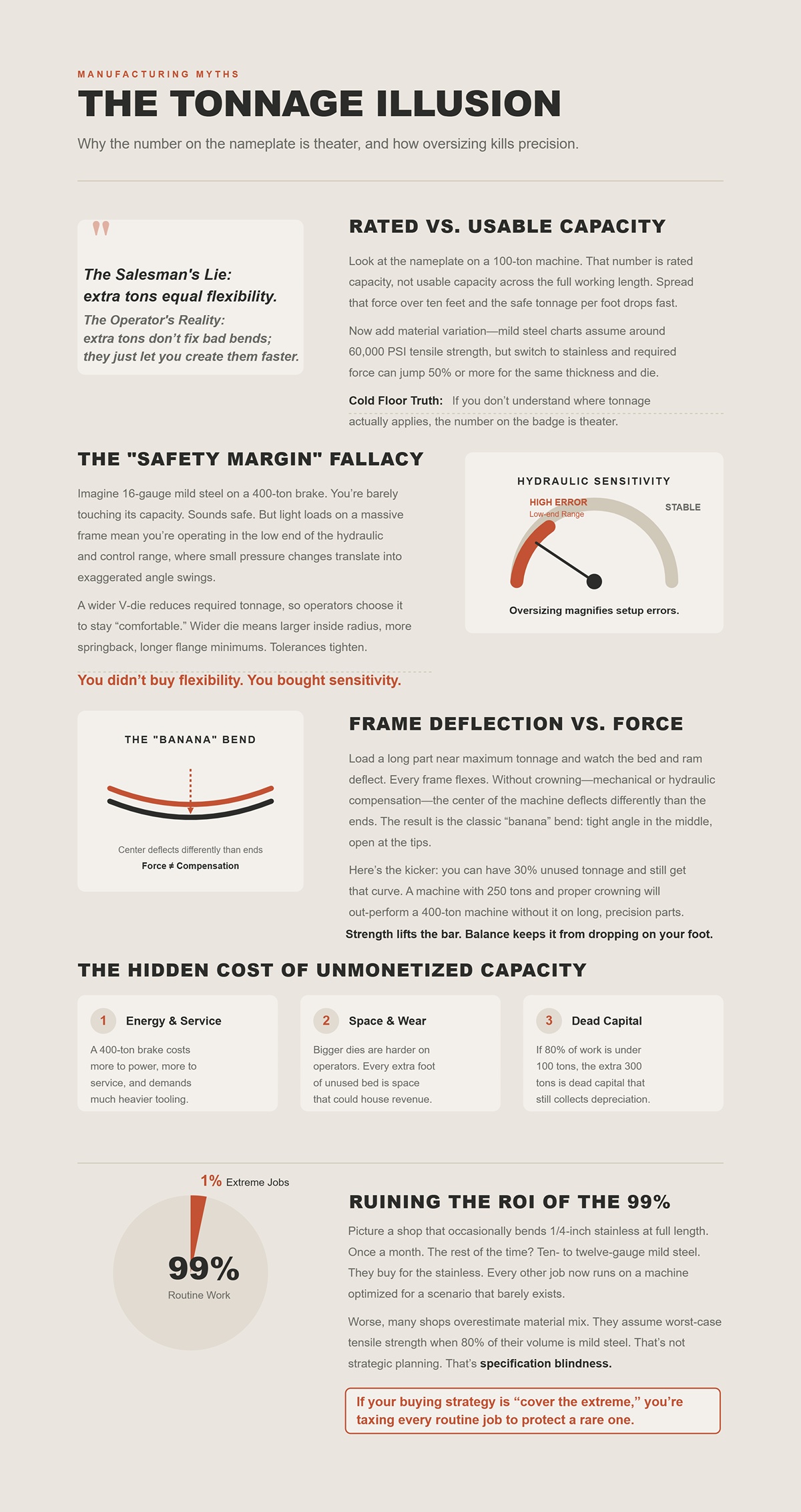
Look at the nameplate on a 100‑ton machine. That number is rated capacity, not usable capacity across the full working length. Spread that force over ten feet and the safe tonnage per foot drops fast. Now add material variation—mild steel charts assume around 60,000 PSI tensile strength, but switch to stainless and required force can jump 50% or more for the same thickness and die.
So shops hedge. They buy 30–50% more tonnage “just in case.”
The Salesman’s Lie: extra tons equal flexibility. The Operator’s Reality: extra tons don’t fix bad bends; they just let you create them faster.
Cold Floor Truth: if you don’t understand where tonnage actually applies—per foot, per material, per die—the number on the badge is theater.
Which raises a harder question: what happens when that “safety margin” becomes the problem?
Imagine 16‑gauge mild steel on a 400‑ton brake. You’re barely touching its capacity. Sounds safe. But light loads on a massive frame mean you’re operating in the low end of the hydraulic and control range, where small pressure changes translate into exaggerated angle swings.
Now add die selection. A wider V‑die reduces required tonnage, so operators often choose it to stay “comfortable.” Wider die means larger inside radius, more springback, longer flange minimums. Geometry shifts. Tolerances tighten. Suddenly your safety margin is a tolerance problem.
You didn’t buy flexibility. You bought sensitivity.
Cold Floor Truth: oversizing doesn’t give you control on light work; it magnifies setup errors.
But even if you size it right, what about the frame itself?
Load a long part near maximum tonnage and watch the bed and ram deflect. Every frame flexes. Without crowning—mechanical or hydraulic compensation—the center of the machine deflects differently than the ends. The result is the classic “banana” bend: tight angle in the middle, open at the tips.
Here’s the kicker: you can have 30% unused tonnage and still get that curve. Force capacity doesn’t prevent uneven deflection; compensation does.
A machine with 250 tons and proper crowning will out‑perform a 400‑ton machine without it on long, precision parts. I’ve watched it happen.
Strength lifts the bar. Balance keeps it from dropping on your foot.
So why do shops still chase bigger numbers?
A 400‑ton brake costs more to power, more to service, and demands heavier tooling. Bigger punches and dies aren’t just expensive—they’re harder on backgauges and operators. Floor space isn’t free either; every extra foot of bed you rarely use is square footage that could house revenue.
And if 80% of your workload is under 100 tons, that extra 300 tons is dead capital. Dead capital still collects depreciation.
That’s scrap‑bin dollars you never see on the quote sheet.
So why do smart shops keep making this bet?
Picture a shop that occasionally bends 1/4‑inch stainless at full length. Once a month. The rest of the time? Ten‑ to twelve‑gauge mild steel brackets. They buy for the stainless. Every other job now runs on a machine optimized for a scenario that barely exists.
Worse, many shops overestimate material mix. They assume worst‑case tensile strength when 80% of their volume is mild steel. That’s not strategic planning. That’s specification blindness.
If your buying strategy is “cover the extreme,” you’re taxing every routine job to protect a rare one.
And that should make you uncomfortable—because if tonnage isn’t the first filter, what is?
A customer brought me parts off two different 10‑foot brakes. Same material: ten‑gauge mild steel, eight feet long. Same punch, same 1‑inch V‑die. One machine was 320 tons with a torsion bar. The other was 220 tons with dual Y1/Y2 hydraulics and active crowning.
The 320‑ton machine had angle spread of almost 1.5° end to end. The 220‑ton held within 0.2° across the length.
Plenty of force in both cases. Only one produced sellable parts without babysitting.
Force creates the bend. Synchronization and crowning decide whether that bend is consistent across eight feet, across the shift, across the batch. Repeatability decides whether your second part matches your first without touching the program. That trio—not tonnage—is what turns a brake from a brute into a production tool.
The Salesman’s Lie: “This machine has more tons than you’ll ever need.” The Operator’s Reality: “I need the ram to land parallel within hundredths and stay there under load.”
Cold Floor Truth: If tonnage isn’t your first filter, synchronization accuracy, crowning strategy, and positional repeatability should be.
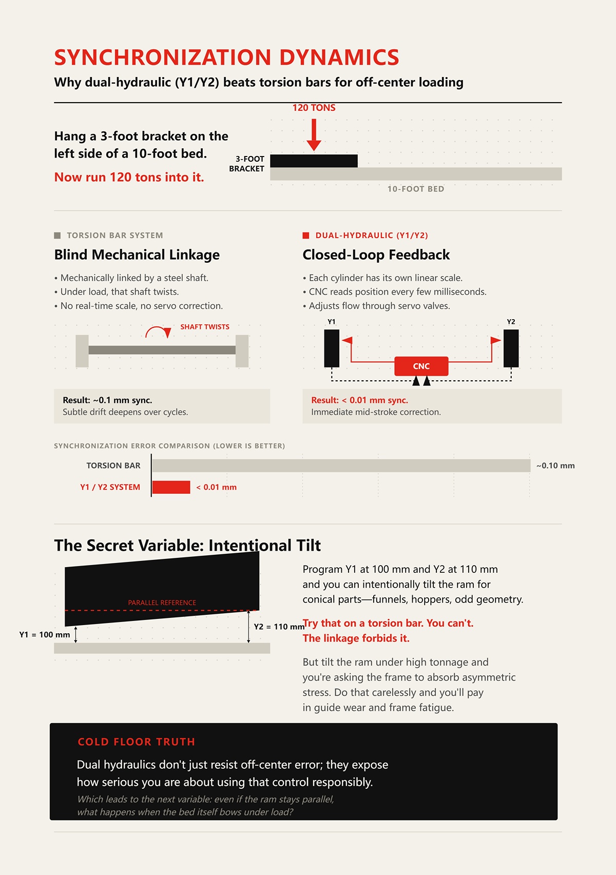
Hang a 3‑foot bracket on the left side of a 10‑foot bed. Now run 120 tons into it.
On a torsion‑bar machine, both sides of the ram are mechanically linked by a steel shaft. Under load, that shaft twists—microns, yes, but enough. There’s no scale reading each side in real time. No servo valve correcting mid‑stroke. You get roughly 0.1 mm synchronization in ideal conditions, but under off‑center load the bar elastically deforms and the machine has no idea it happened.
The result isn’t dramatic. It’s worse than that. It’s subtle drift—one side slightly deeper, accumulating over cycles as heat and wear creep in.
On a dual‑hydraulic Y1/Y2 system, each cylinder has its own linear scale. The CNC reads position every few milliseconds and adjusts flow through servo valves to keep both sides synchronized to within hundredths—sub‑0.01 mm in good systems. Off‑center load shows up immediately as position error, and the control corrects it during the stroke.
That’s the mechanism. Closed‑loop feedback versus blind mechanical linkage.
Now, here’s the part the brochure skips. Program Y1 at 100 mm and Y2 at 110 mm and you can intentionally tilt the ram for conical parts—funnels, hoppers, odd geometry. Try that on a torsion bar. You can’t. The linkage forbids it.
But tilt the ram under high tonnage and you’re asking the frame to absorb asymmetric stress. Do that carelessly and you’ll pay in guide wear and frame fatigue.
So synchronization is power—but only when the frame and programming discipline match it.
Cold Floor Truth: Dual hydraulics don’t just resist off‑center error; they expose how serious you are about using that control responsibly.
Which leads to the next variable: even if the ram stays parallel, what happens when the bed itself bows under load?
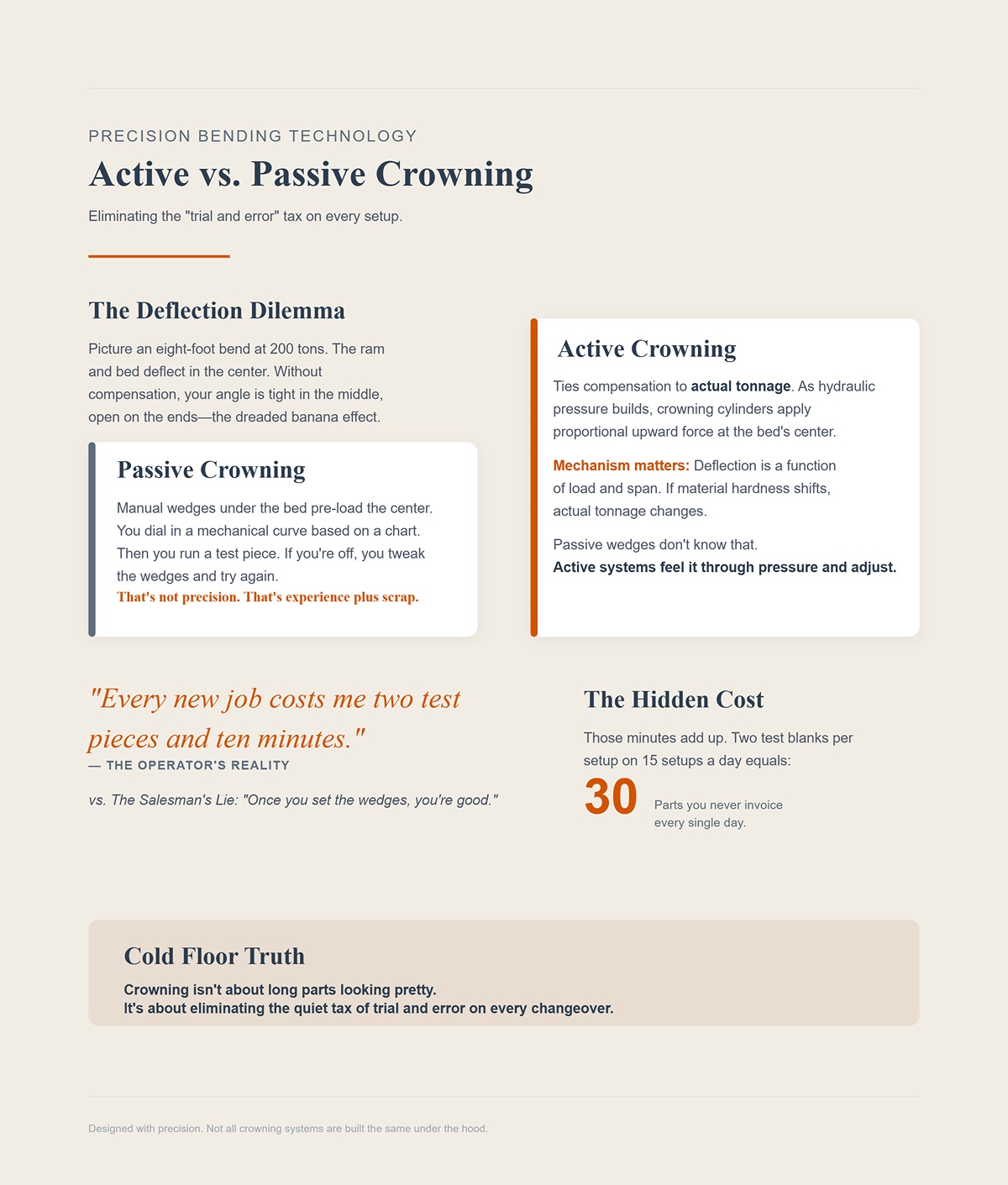
Picture an eight‑foot bend at 200 tons. The ram and bed deflect in the center. Without compensation, your angle is tight in the middle, open on the ends—the banana we talked about earlier.
A passive crowning system—manual wedges under the bed—lets you pre‑load the center. You dial in a mechanical curve based on a chart: material, thickness, length, estimated tonnage. Then you run a test piece. If you’re off, you tweak the wedges and try again.
That’s not precision. That’s experience plus scrap.
Active crowning ties compensation to actual tonnage. As hydraulic pressure builds, the crowning cylinders apply proportional upward force at the bed’s center. The system bends the bed opposite the ram’s deflection in real time.
Mechanism matters here. Deflection is a function of load and span. If your material hardness shifts—say mild steel one batch, higher tensile the next—the actual tonnage at the same programmed depth changes. Passive wedges don’t know that. Active systems feel it through pressure and adjust.
The difference shows up in setup time. On high‑mix work, passive crowning means test‑bend, measure, adjust. Active crowning means first‑part accuracy far more often.
The Salesman’s Lie: “Once you set the wedges, you’re good.” The Operator’s Reality: “Every new job costs me two test pieces and ten minutes.”
Those minutes add up. Two test blanks per setup on 15 setups a day is 30 parts you never invoice.
Cold Floor Truth: Crowning isn’t about long parts looking pretty. It’s about eliminating the quiet tax of trial and error on every changeover.
But not all crowning systems are built the same under the hood.
Let’s say yesterday’s ten‑gauge mild steel tested around 60,000 PSI tensile strength. Today’s batch runs closer to 70,000. Same thickness. Same program.
Required tonnage increases. Deflection increases with it.
Mechanical wedge systems are static. You set them based on estimated tonnage. If actual load climbs 15%, your compensation is now under‑corrected. Angle opens at the ends again. You compensate at the ram depth, which shifts your inside radius and flange geometry.
Hydraulic crowning systems tied to pressure react to the real load. Higher tonnage generates higher crowning force automatically. The bed curve tracks the ram deflection curve.
There’s complexity here—servo valves, seals, sensors. They cost more upfront and demand maintenance discipline. In a low‑variety shop running the same part for weeks, mechanical wedges can make financial sense.
But in a high‑mix environment where material batches and part lengths change daily, hydraulic crowning keeps angle uniform without re‑engineering the setup every time.
This is where ROI lives. Not in peak tonnage, but in how little the machine cares when the material isn’t textbook.
Cold Floor Truth: If your material varies, static compensation becomes guesswork. Guesswork is just scrap wearing a different hat.
So the ram is parallel. The bed is compensated. What about the part location itself?
I’ve seen shops brag about 1,000 mm/sec backgauge speed. Sounds impressive—until you measure repeatability.
Take a bracket with four bends, all referenced from the first flange. If your backgauge repeats within ±0.05 mm, your hole patterns line up in welding. If it drifts ±0.3 mm, you’re forcing parts into fixtures, grinding tabs, blaming the laser.
Travel speed affects cycle time. Repeatability affects whether the assembly fits.
High‑quality backgauges use precision ball screws, rigid fingers, and encoders that close the loop on position. Cheap systems rely on step counting and open‑loop assumptions. Over thousands of cycles, backlash and wear show up as dimensional creep.
Here’s the connection most people miss: synchronization and crowning keep the angle consistent. Backgauge repeatability keeps the flange length consistent. Angle plus length equals geometry. Geometry determines fit‑up.
You can have perfect tonnage, beautiful paint, and still ship parts that fight the welder.
The Salesman’s Lie: “It’s fast.” The Operator’s Reality: “Does the tenth part fit like the first?”
Cold Floor Truth: Speed makes parts quickly. Repeatability makes parts that go together.
And once you start stacking axes—R, Z1, Z2, X1, X2—the question isn’t how many you have. It’s whether that added complexity strengthens this trifecta… or quietly undermines it.
You’ve got synchronization. You’ve got active crowning. Your backgauge repeats within a few hundredths. Now the brochure slides across the table and says: add R, add Z1/Z2, add X1/X2. Six axes. Eight axes. Fully automatic.
So here’s the real question: do those extra axes strengthen the quality trifecta—or do they just multiply the ways you can lose it?
A press brake is a weightlifter. Brute strength looks good in a catalog photo. But without balance and timing, the bar wobbles. In a shop, that wobble shows up as inconsistent flange lengths, wrong bend sequences, and parts that only fit after a grinder “adjusts” them. More axes add coordination demands. Coordination is software, servo response, and operator judgment stacked on top of each other.
Axes don’t create precision. They demand it.
Cold Floor Truth: Every new axis is another moving part that must stay in sync with the trifecta—or it becomes a very expensive way to make scrap faster.
Let’s get concrete.
A basic 2- or 3+1-axis setup—Y1/Y2 for ram control, X for backgauge depth, maybe R for vertical gauge height—handles the majority of bracket and enclosure work I see in mid-size shops. Flange lengths are consistent. Sequences are simple. Operators adjust stops by feel and experience.
Cycle time bottleneck? Usually material handling. Or walking back to the rack. Not axis travel.
Now drop in a 6-axis backgauge with independent Z1/Z2 fingers and programmable R movement. On asymmetrical parts—offset flanges, reverse bends, parts that can’t be flipped—that system can eliminate manual repositioning between bends. That’s real productivity when geometry demands it.
But here’s what I watch on the floor: the first setup takes longer. Programming the sequence for independent finger travel, checking for collisions, teaching the machine the part orientation—it eats time. If 80% of your jobs are simple, that complexity doesn’t remove a bottleneck. It creates one.
The Salesman’s Lie: “More axes mean less operator work.” The Operator’s Reality: “More axes mean more decisions before I make the first good part.”
Cold Floor Truth: If your bottleneck isn’t backgauge repositioning, six axes won’t fix it.
Z1/Z2 independence shines on parts that are asymmetrical across the bend line. Think a panel where the left flange is 40 mm and the right is 65 mm, and you can’t flip the part because of upstream features. Independent fingers let each side support its own reference without manual sliding.
That’s essential when the part design forces it.
Now imagine high-volume brackets with identical flanges left and right. Ten-gauge mild steel, eight feet long. Straight bends, same reference edge every time. Programming Z1/Z2 to move independently for minor variations is like putting power seats in a forklift—nice, but not what makes it earn money.
And here’s the part vendors don’t emphasize: independent movement demands precise calibration between the two fingers. If one servo drifts or one ball screw develops backlash, your “independent precision” becomes independent error. Now your synchronization and crowning are perfect—but your reference edge shifts a tenth here, two tenths there.
Angle plus length equals geometry. You can’t afford either wandering.
Cold Floor Truth: Z1/Z2 is a tool for design constraints—not a status symbol for the spec sheet.
Here’s where things get ugly.
Each axis—X, R, Z1, Z2, X1, X2—relies on servo drives and a controller that coordinates motion. When the controller can’t process and execute those moves fast enough, you get lag. Not visible lag. Millisecond lag.
But at the bottom of the stroke, milliseconds matter.
Y1/Y2 ram synchronization keeps the beam parallel. Add complex backgauge moves that must clear, reposition, and settle before the bend completes, and you’re stacking timing events. If the control isn’t up to it, the ram may hit depth before the gauge is fully settled. Or the gauge settles, but the position feedback hasn’t fully stabilized.
That’s how you get the first part good, the fifth part questionable, and the tenth part in the scrap bin.
The machine still says “six axes.” The scrap bin says “controller mismatch.”
Imagine 16-gauge mild steel on a 400-ton brake. Massive capacity. Now imagine the controller choking on simultaneous axis commands. The problem isn’t strength. It’s coordination under load. Same story.
Cold Floor Truth: High axis counts without a controller that can truly synchronize them is just complexity outrunning control.
Here’s the uncomfortable truth most owners learn the hard way.
If you’re running 500 identical parts, simple geometry, same material all week, a well-synced 3+1-axis machine with active crowning will often outproduce a fully loaded 6+1-axis system. Fewer parameters. Faster programming. Less to go wrong.
Manual tweaks—slide a finger, bump a stop—take seconds when the operator knows the job. Programming independent axes for minor differences can take minutes. Minutes multiplied across small batches is real money.
Now flip it.
If you’re high-mix, low-volume, complex geometries changing every hour, advanced axes tied to a fast controller and good offline programming can cut setup scrap and eliminate repeated manual repositioning. That’s where they pay.
So the right question isn’t “How many axes can I afford?” It’s “What does my work actually demand, and can my people and controller support it?”
Cold Floor Truth: More axes increase potential. They also increase the cost of every mistake.
And that’s the bridge to the only comparison that matters next—matching specific shop types to specific configurations, instead of buying the biggest weightlifter on the poster and hoping balance shows up for free.
Last winter I walked through three shops in one week. One ran 20 different part numbers before lunch. One bent nothing but 3/8 and 1/2 plate for stair stringers. The third was installing its first robot. All three were shopping “more tonnage.”
Same salesman. Three completely different realities.
The question isn’t how many axes you can bolt on. It’s what 80% of your day actually looks like — and whether your synchronization and crowning strategy protect you there. Because force without deflection control is just an expensive way to make consistent scrap. And axes without a workload to justify them are just software menus waiting for a mistake.
So which configurations actually fit?
Picture a job board with 30 travelers clipped up. 14‑gauge today, 11‑gauge next, then a stainless enclosure that always springs back differently than the print suggests.
Here’s the part most shops misdiagnose: a 10% increase in tensile strength requires roughly 10% more force — and about 10% more crowning to keep the ram and bed parallel under load. A 10% thickness jump? You’re closer to 20% more pressure. If your crowning is mechanical and static, it cannot adjust under load. The operator sees the angle open up mid‑length and blames springback.
But the beam is deflecting.
Hydraulic or CNC crowning systems that adjust dynamically during the bend are what keep high‑mix shops sane. Not because they’re flashy — because they react when material reality doesn’t match the calculator. Without that, your “10‑minute changeover” becomes 10 minutes plus three test pieces.
Now stress-test that. Even with multi‑zone CNC crowning, the system assumes ideal material behavior. Real steel varies. You still need an operator who understands what he’s seeing. Fast backgauges and independent Z1/Z2 fingers help when geometry forces them — but if your crowning can’t track thickness and tensile swings, your speed elsewhere doesn’t matter.
The Salesman’s Lie: “Six-axis backgauge cuts setup time.” The Operator’s Reality: “If the angle’s drifting, I’m chasing it no matter how fast the fingers move.”
Cold Floor Truth: In high-mix work, dynamic crowning accuracy saves more scrap-bin dollars than an extra backgauge axis ever will.
But what if your parts rarely change — and your problem isn’t variability, it’s mass?
Imagine 1/2-inch plate, 10 feet long. Two bends per part. All day.
Thickness shifts 10%. That’s about 20% more required force. On heavy plate, that jump isn’t theoretical — it’s what happens when a mill run changes. If your frame isn’t rigid enough, no amount of programmed crowning will fully rescue you. The ram and bed stay compensated, but the side frames themselves breathe.
Even with perfect crowning, studies show angle variation can sit within about ±0.3 degrees from material variability alone in quarter-inch plate. When I see shops missing by more than that, the culprit usually isn’t crowning — it’s frame deflection or poor Y1/Y2 synchronization under load.
Here’s where the spec sheet tricks you. Cycle speed looks impressive. Axis count looks modern. But heavy fab lives in full stroke, deep throat, and frame mass. If you can’t physically fit the part because throat depth is short, or you’re bottoming out stroke before clearing a return flange, all the servo speed in the world won’t help.
The Salesman’s Lie: “You’ve got 500 tons. You’re covered.” The Operator’s Reality: “If the frame twists, I’m bending a banana.”
Cold Floor Truth: In structural work, rigidity and geometry envelope beat cycle speed every time — and crowning must scale with thickness swings, not just tonnage capacity.
Now what happens when today’s manual shop plans to bolt a robot on next year?
A human operator compensates subconsciously. If the flange comes out a hair long, he adjusts grip pressure, re-seats the part, tweaks depth on the fly.
A robot does exactly what you told it. No more. No less.
That’s where additional axes — programmable R-axis height, Z1/Z2 positioning, sometimes even X1/X2 depth — stop being luxuries and start being requirements. The robot needs predictable gauge positions and collision-free motion paths. Independent finger movement that felt like overkill in manual mode becomes essential when a gripper can’t “feel” its way around a misaligned stop.
But here’s the trap: adding axes for future automation without upgrading controller speed and synchronization is how you build a very expensive hesitation machine. Robots hate waiting on slow backgauges. They also hate angle drift. If crowning isn’t dynamic and repeatable, your robot will faithfully produce identical scrap.
Cold Floor Truth: Plan axes around tomorrow’s automation only if your control and crowning are strong enough to make repetition an asset, not a liability.
And sometimes the smartest automation move isn’t more axes on one machine at all.
I’ve seen shops price a 1,000‑ton monster to handle occasional 20‑foot parts.
Then I’ve seen two 500‑ton machines run in tandem for long parts — and uncoupled for daily work.
On paper, the single giant brake looks simpler. One frame. One control. Big number on the brochure. But most shops don’t bend 20‑foot parts all day. They bend Ten‑gauge mild steel, eight feet long, brackets and channels that would tie up that monster at a fraction of its capacity.
Two smaller, well-synchronized machines give you options. Run them together when length demands it. Split them and double throughput on standard work the rest of the week. If one goes down, you’re not dead in the water.
But even here, synchronization is king. Tandem mode demands tight Y1/Y2 control across both frames and coordinated crowning strategies. If one machine deflects differently, you’ll see it in the middle of the part.
The Salesman’s Lie: “Buy once. Go big.” The Operator’s Reality: “Most days, I need balance — not a billboard.”
Cold Floor Truth: The best press brake isn’t the strongest weightlifter on the poster. It’s the one whose control, crowning, and configuration match the work you actually run 80% of the time.
And once you see that, the spec sheet starts looking a lot less like a trophy — and a lot more like a trap waiting for misinterpretation.
Given all these variables, how does a shop actually decide?
You stop shopping by headline numbers and start reading the fine print like it’s a contract written against you.
A spec sheet is a poster of a weightlifter mid‑press: big number, chest out, bar overhead. Impressive. But the poster doesn’t show whether he can hold the bar steady, or if his knees cave in under load. And in a shop, when the bar drops, it lands in the scrap bin.
The salesman sells peak force. The floor pays for deflection, setup time, and angle drift.
If you don’t know how to decode a quote, you’ll compare machines that aren’t even playing the same game.
“400 tons.”
At what distance?
Tonnage ratings are tied to a specific span between side frames and a specific load distribution. Change the distance from the centerline. Change the die opening. Change the material width. The available force per foot shifts, and so does deflection.
Now layer in the unit games. One vendor quotes short tons per foot. Another quotes metric tons per meter. They look close enough on paper to feel comparable. They aren’t. I’ve seen shops think they were getting a 10% stronger machine when they were just reading two different measuring sticks.
The Salesman’s Lie: “It’s a 300‑ton machine.” The Operator’s Reality: “At my working length and die, it behaves like 240.”
And here’s where it gets subtle. You can lower required tonnage by opening the V‑die from 8× material thickness to 12×. Force drops nicely on the chart. But your inside radius grows, flange geometry changes, and suddenly your part doesn’t seat against the gauge the way it used to. You saved tonnage and bought yourself fit‑up headaches.
Cold Floor Truth: Rated tonnage is a conditional promise, not a universal truth — and if you don’t match the condition to your real parts, you’re budgeting with fantasy numbers.
So if force isn’t absolute, can software smooth over the gaps?
Modern controls will simulate the bend before the ram moves. Material library. Springback compensation. Collision detection. It looks surgical.
But the simulation assumes the frame behaves the way the model predicts.
Hydraulic machines and electric machines don’t deliver force the same way. Electric drives apply force more precisely, but often with different speed and stroke characteristics. If the software’s bending model leans on hydraulic assumptions about dwell or pressure build‑up, you can end up with a beautiful simulation and a real‑world angle miss.
Imagine 16‑gauge mild steel on a 400‑ton brake. The simulation says you’re at 20% capacity. Plenty of headroom. But if synchronization under light load isn’t tight — if Y1/Y2 aren’t perfectly tracking — that “easy” job shows a taper from left to right. Not because you lacked force. Because you lacked control at low force.
The Salesman’s Lie: “The control calculates everything.” The Operator’s Reality: “The control can’t stiffen a frame.”
Cold Floor Truth: Software predicts force; it cannot cancel physics. If the iron twists, the code just documents the twist.
And even if the machine is perfectly synchronized, can you physically run your parts through it day after day?
This is where deals quietly die.
Daylight is the open distance between ram and bed. Stroke is how far the ram travels. Throat depth is how far back you can get a flange before you hit the frame. None of these look heroic on a brochure. All of them decide whether your part fits.
I’ve watched shops buy for tonnage and then discover they can’t clear a return flange without custom tooling or flipping the part three times. Each flip adds handling time. Each handling move adds variability. Your theoretical cycle time evaporates in human motion.
Tooling compatibility is the same story. If the machine takes proprietary punches that cost 30% more per station, that’s scrap‑bin dollars hiding in capital expense. Over five years, that delta can equal a servo upgrade you actually needed.
But even if you size it right, what about the frame itself?
Cold Floor Truth: A brake that can’t comfortably fit your 80% parts is not “versatile.” It’s a daily compromise that taxes every shift.
So maybe you focus on speed instead.
Approach speed is how fast the ram travels before it contacts material. Bending speed is how fast it moves under load.
Guess which one gets printed bigger.
If your cycle is dominated by handling — load, align, gauge, unload — shaving half a second off approach speed won’t change your throughput. If you’re air bending thin parts with short strokes all day, then approach speed matters more. Context decides.
Heavy plate tells a different story. Under load, bending speed often slows to protect the frame and maintain accuracy. That’s not a flaw. That’s physics and good engineering. A machine that screams down fast but crawls unpredictably under load will wreck your rhythm and your angles.
The Salesman’s Lie: “This one is 30% faster.” The Operator’s Reality: “Show me the speed at full load, at my working length.”
Cold Floor Truth: The only speed that pays is the one that survives contact with material — and stays accurate while doing it.
Strip away the hype, and the pattern is clear: every impressive number on a quote has a condition attached.
So the real question isn’t which spec is bigger.
It’s which conditions match your floor.
If every spec is conditional, you don’t compare machines by their maximums — you compare them by how they behave on your most common parts.
Pull your last 12 months of bending jobs. Not the hero piece you show customers. The boring stack: brackets, covers, frames, enclosures. List material, thickness, bend length, inside radius, tolerance. You’ll see a pattern. Most shops do.
The mistake is shopping for the loudest 5% of that list.
The Salesman’s Lie: “You’ll grow into the extra tonnage.” The Operator’s Reality: “I’ll pay for it every day on parts that never needed it.”
A brake is a weightlifter. Brute strength looks great on the poster. But without balance and control, all you’re doing is dropping the bar — and in a shop, that bar lands in the scrap bin.
Cold Floor Truth: Buy the machine that makes your common jobs faster and cleaner, not the one that flexes hardest on your rarest part.
So how do you turn that into a spec sheet that actually means something?
Start with your heaviest recurring job, not the once-a-year monster. If you routinely bend ten‑gauge mild steel, eight feet long, that’s your anchor. Calculate tonnage for your real die openings and real materials — and be honest about stainless versus mild, because die choice alone can swing required force dramatically.
Now apply the frame rule most brochures whisper about: full tonnage should be spread over at least 60% of the distance between side frames. On a 10‑foot machine, that means you don’t get to dump max force into a three‑foot section without inviting permanent deformation.
This is where buyers overcorrect. They see variability in tonnage charts and jump a size “to be safe.” But if your true 80% workload lives at 65–75% of rated capacity, you’re in the Goldilocks zone: enough headroom for material swings, not so much machine that you’re paying for unused iron.
The non‑obvious part? Oversizing can make partial‑length bends riskier, not safer. Big machine. Short part. High localized load. You thought you bought insurance; you bought stress concentration.
Cold Floor Truth: Size for the heaviest job you actually run weekly — and make sure that load sits comfortably inside the machine’s structural sweet spot, not on its bragging limit.
But tonnage only sets the ceiling. What keeps parts consistent across that span?
You’re not buying force. You’re buying controlled force.
Ask these, and don’t accept hand-waving:
How is crowning applied — manual wedges, hydraulic, or CNC-controlled dynamic crowning tied to tonnage?
If adjustment isn’t automatic and repeatable, you’re tuning by feel. That’s ±1.0° waiting to happen.
Is crowning calculated from real-time load feedback or preset tables?
Presets assume ideal material. Real steel doesn’t read brochures.
How is Y1/Y2 synchronization measured and corrected under light load and asymmetrical loading?
Imagine 16‑gauge mild steel on a 400‑ton brake. Low percentage of capacity. If the rams drift even slightly, you’ll see taper before you feel force.
What’s the demonstrated angle variation across full working length on a standard air bend?
Not theoretical. Show parts. Put a protractor on them.
What happens to angle consistency at 70% of rated tonnage over eight feet?
That’s where most real work lives. Not at 100%. Not at 10%.
The Salesman’s Lie: “It has CNC crowning and closed-loop sync.” The Operator’s Reality: “Closed-loop of what, corrected how, and proven on which material?”
If they can’t answer cleanly, you’ve found your gap.
And that gap is where scrap is born.
Stop asking, “What’s the maximum tonnage?” Start asking, “How many first-piece hits do we get per shift?”
Here’s a hypothetical that plays out every week: Shop A buys a 250‑ton hydraulic brake for security. Shop B buys a 180‑ton electric with tight synchronization and automatic crowning. Both can technically form the workload.
Shop A spends three test bends dialing angle across length. Shop B hits tolerance on the second piece because the machine compensates for deflection automatically. Multiply that by 20 setups a week.
The difference isn’t horsepower. It’s time and scrap wearing a different hat.
Measure ROI in three buckets:
If a smaller, better‑controlled machine cuts setup by even five minutes per job in a high‑mix environment, that’s hours a week. Hours become capacity. Capacity becomes margin.
Force without deflection compensation is simply an expensive way to generate scrap.
The new lens is this: treat tonnage as a constraint to clear, then rank machines by how intelligently they manage deflection, synchronization, and repeatability inside your 80% workload. When you evaluate that way, the biggest number on the quote stops being impressive — and starts being irrelevant.


